7mm Mickoo's Commercial Workbench

Clarence3815

Western Thunderer
Reminds me of a remark our solicitor made about a relative who was being difficult over the will of an Aunty.

`Sour and ungracious`.

I hope nobody ever uses that description of me.

Bernard
 

mickoo

Western Thunderer
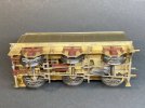
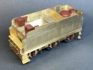
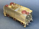
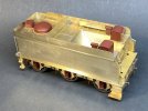
Tally Ho, onward with the next build, a JLTRT Castle, two in fact. One from the 50xx series, the other from the 70xx series so it'll be interesting to work through the sub class differences and details.

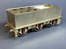
I've trodden this road before, more so the 4000G tender so all the areas to pay attention to are known. Like last time the tender white metal was junk, a brief glance in the bag showed it wasn't even worth opening to inspect; it all went in the bin and the 3D monkeys were instructed to reprint the last lot.

Like last time, the brass etches are a doddle, they fit where they touch....which is in all the right places....so it doesn't take long to build up. I'd allowed three days, but realistically it'll be four and hopefully finished tomorrow.

Like last time the coal space front overlay is a smidge short height wise, but unlike last time I left the gap at the bottom, it'll get covered with a small strip and because it's under the footplate will barely be seen. Last time I butted it up to the floor and had to fill the gap at the top which is in full view, not impossible or even difficult, just time consuming.

The only parts missing from the tender box were the nuts and bolts pack and the 5/32" bearings so on that score it's leaps and bounds ahead of the last two JLTRT kits I've done.

Img_1509.jpeg

Img_1510.jpeg

Img_1511.jpeg
 
Last edited:

mickoo

Western Thunderer
Sometimes you just have to accept things are going to take longer than envisaged.

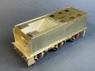
Virtually finished but thwarted by JLTRT packing again, there are three stantions in the kit, none of which resemble anything like that which should be fitted to this type of tender that I'm aware of, two of them I do not recognize and may even be another region. I'll draw up some new ones and 3D print with a wire core for strength like the recent Crab tomorrow.

My coal hopper floor is oddly too short so it's not been fitted, for a few of reasons; it's too short, I'm have no enthusiasm at the end of this day to cut a new one and I'm not 100% sure the front footplate is the right height.

Looking at photographs the floor is the same height as the lower longitudinal row of rivets so that's what's been fitted; yet the previous King class was a good 6" lower and used the other set of risers. I'll wait until the chassis and cab floor are done to cross check the floor heights and then add the coal hopper floor.

There's a gap between the sloped sides and tank top, more than last time and I can't see why, it is what it is so will need dealing with. It's too big to flood fill with solder so will need some backing put in (probably epoxy), then the gap filled with Milliput and smoothed off.

Img_1532.jpeg

Img_1533.jpeg

Img_1535.jpeg
 

mswjr

Western Thunderer
well every day is a school day, I never new they had balance weights , I must look at Bulleid wheels more closely next time.
 

John Walker

Active Member
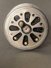
Mick, after your assertions I have had a closer look at my archives and found these. They were taken on open days at Herston. This is Sir Keith Park with plates on both sides of the wheel.

Skpdsc04286-1.jpg

This is 257 Squadron with evidence of a plate on the back only:

257dsc01193-1.jpg


Looks like more research is required!

Regards
John Walker
 

mickoo

Western Thunderer
Mick, after your assertions I have had a closer look at my archives and found these. They were taken on open days at Herston. This is Sir Keith Park with plates on both sides of the wheel.

View attachment 215386

This is 257 Squadron with evidence of a plate on the back only:

View attachment 215387


Looks like more research is required!

Regards
John Walker

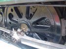
Rebuilt Bulleids have extra weight by adding a plate on the front as well as the rear, but only on rebuilds.

Originals have a plate only on the rear plus the two adjoining cavities filled.

For what it's worth, 257 Squadron has a rebuilt driver with associated crankpin (four bolted studs) but not the extra sheet weight.
 
Last edited:

Pencarrow

Western Thunderer
Rebuilt Bulleids have extra weight by adding a plate on the front as well as the rear, but only on rebuilds.

Originals have a plate only on the rear plus the two adjoining cavities filled.

For what it's worth, 257 Squadron has a rebuilt driver with associated crankpin (four bolted studs) but not the extra sheet weight.

The extra balance weight being necessary when the oil bath and Bulleid gear was removed and replaced with conventional parts which has extra rotating mass to balance.
 

mickoo

Western Thunderer
The extra balance weight being necessary when the oil bath and Bulleid gear was removed and replaced with conventional parts which has extra rotating mass to balance.
Well sort of, the only extra mass is the eccentric sheave (there's only one which is confusing me at the moment unless the inside valve is derived and this is some sort of fulcrum offset rod) and the outside return cranks of which part of the mass is near the wheel centre, I'd not think either of those items have enough mass to require the slab on the outside, but there must be a reason.

All of the other valve gear is not loaded onto the rotational mass of the driving wheel.

IMG_0974.jpg
 
Last edited:

James Spooner

Western Thunderer
Well sort of, the only extra mass is the eccentric sheave (there's only one which is confusing me at the moment unless the inside valve is derived and this is some sort of fulcrum offset rod) and the outside return cranks of which part of the mass is near the wheel centre, I'd not think either of those items have enough mass to require the slab on the outside, but there must be a reason.

All of the other valve gear is not loaded onto the rotational mass of the driving wheel.

View attachment 215460
One eccentric sheath is correct as it is Walschaerts so it drives the inside gear version of the return crank rod (an eccentric rod as it is driven by the eccentric) and connects to the expansion link. There is a good drawing of one on the Bulleid society website here: https://www.bulleidsociety.org/34059/Pictures/Valve_Gear/rebuild_valve_gear.gif

Nigel
 

mickoo

Western Thunderer
One eccentric sheath is correct as it is Walschaerts so it drives the inside gear version of the return crank rod (an eccentric rod as it is driven by the eccentric) and connects to the expansion link. There is a good drawing of one on the Bulleid society website here: https://www.bulleidsociety.org/34059/Pictures/Valve_Gear/rebuild_valve_gear.gif

Nigel
Facepalm….. of course it does, I was thinking of the more common twin sheave set up for Stephenson arrangement.
 

Pencarrow

Western Thunderer
Well sort of, the only extra mass is the eccentric sheave (there's only one which is confusing me at the moment unless the inside valve is derived and this is some sort of fulcrum offset rod) and the outside return cranks of which part of the mass is near the wheel centre, I'd not think either of those items have enough mass to require the slab on the outside, but there must be a reason.

All of the other valve gear is not loaded onto the rotational mass of the driving wheel.

View attachment 215460
Going to have to dig out my Bulleid books and see if they mention the reason for the extra balance weights. The rebuilt Bulleids were heavier and the increased axle loading was the reason why they didn't go to Padstow and a few other places the originals went. I was also convinced that I read previously the hammer blow was heavier in the rebuilt versions. Never really looked into the internal differences before...
 

simond

Western Thunderer
I guess it’s possible that the re-weighting was not actually optimal…

it’s a long, long time since university, but Mick’s comment at the end of #2991 which I interpreted as not balancing reciprocating masses rang alarm bells. I recall that there were some guidelines about proportions of the weights of eg con rods that would be considered in (IC) engine balancing.
 

J_F_S

Western Thunderer
The extra balance weight being necessary when the oil bath and Bulleid gear was removed and replaced with conventional parts which has extra rotating mass to balance.

Partly so - if I understand correctly - rebalancing was also needed after Biddy Line broke a crank axle passing through Crewekerne. One cause of fatigue was the very high forces due to the unbalanced rotating mass on the crank axle. Balanced crank webs were then fitted and this reduced the balance needed on the wheels.

So although the locos were rebalanced on re-build, the history of what weights were applied to any particualr wheelset and when, might be complex.

Hope that helps
 

J_F_S

Western Thunderer
Mick’s comment at the end of #2991 which I interpreted as not balancing reciprocating masses rang alarm bells.

Bulleid took a calculated risk with 0% recip. balance in order to save weight. It paid off in the sense that the locos were 'smooth running' but that ignores the high stress through the axles due to the unbalanced couples. Whilst the reciprocating masses in a 120 deg 3-cylinder loco with non-divided drive are statically in balance, the remaining couples (due to the cylinder axises not being in the same vertical plane) are very pronounced at any kind of rotational speed, and for that reason, the locos were re-balanced more conventionally as per my post above. Chapelon is quoted as being very critical of this (and other aspects of Bulleid's design) and quotes wheel deflections of 25mm dues to crank axle forces on the four cylinder compounds. Chapelon and Bullied were on freindly terms, but any advice offered was clearly not listened to! I seem to recall that on rebuilding, the balance was redistributed acroos all three axles - but I would be hard pressed to quote a source for that!

Edit:- I also believe that the reason for the rebuilds being banned from Meldon Viaduct was due the hammer blow from the re-balance (with 0% recip balance the originals had zero hammer blow) rather than their increased axle load.
 
Last edited:

simond

Western Thunderer
Thanks Howard,

As I said, long time gone, but I do recall that there were various "schools of thought" regarding balancing the bits that reciprocate at one end and circulate at the other. I was concerned with IC engines, but it appears that the debate had been going on for some time.

I guess a bit of CAD and programming and it's all dead easy to optimise (at least for some conditions) nowadays. I was writing thermodynamic simulations for 2S engines in HP basic on a single line display, with a till-roll printer and micro cassettes for data storage. The kids today... rant, mutter...
 

mickoo

Western Thunderer
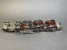
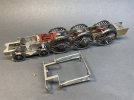
More JLTRT Castle build.

Disclaimer, I have wandered so far off the path it's ridiculous, not because I have to, but because I choose to and the meandering is all for a very good reason.....I reserve the right to review and change that point of view at the end 1f923.png

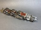
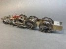
Like the King the kit is designed to have a removable front end but that kind of makes it very difficult to add the massive signature inside motion casting that basically bridges across the joint.

The joining pieces were all removed and the front end grafted onto the rear section and then the next problem was tackled. I had a lot of problems (self inflicted, not having a clue what to do, moons not aligned....you name it) sorting the inside slide bars and cross heads on the King as they were trapped inside the engine, it didn't make painting/masking very easy or cleaning up and running in afterward easy either.

My other problem is AGH wheels, you can't just pop them off the axles like Slaters and wriggle them past the slide bars, ergo the slide bars have to be made removable and thus the outside cylinder blocks.

You could make the brake gear and springs removable but the springs are 3D and the brake gear....if you want to model it with any sort of accuracy is a jumble of pull rods, return cranks and counter pull rods; all in all a lot of work and then there's still the inside motion at the front end that has to come out.

The final solution is the outside cylinders, slide bars and inside motion will all be one unit that drops in from the top...it'll become more clearer as it progress; there's still more prep work and supports to be added to the chassis to achieve that.

The leading axle box, springs and hangers differs in that it has the brake shaft trunnion casting grafted on so those'll be in the machine over night once the ash pan has finished, then I can work on all the brake gear, safe in the knowledge that once in, it can stay in.
Img_1554.jpeg

Img_1555.jpeg

Img_1556.jpeg

Img_1557.jpeg
 
Top