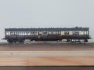
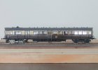
2mm Modbury

Ian Smith

Western Thunderer
Modbury always has been a layout I'd travel quite a distance to see. The chance of seeing this working on the layout means the distance has increased considerably.
Mike, Thankyou for those kind words! I don’t know where in the country you are based, but Modbury will be at RailWells in August and at the Aldershot exhibition in October, and all being well will be at RailEx at Stoke Mandeville next May.
Ian
 

paratom

Western Thunderer
Just coming off my workbench is my first 2mm scale signal (actually it's my first completed signal in any scale!)

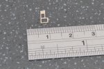
This one is the Down Home for my fictional Modbury layout. The post has been milled to a tapered profile from 3mm square brass bar, the arm, balance weight and ladder are MSE components. The lamp is my own turning fixed to a small piece of L section brass. The finial is an old (overscale) OO handrail knob with a piece of 0.5mm phosphor bronze wire pushed through, soldered and turned to a point in a mini drill. The base of the finial is a small scrap of 0.010" (or 0.008" - can't remember) nickel silver with a 0.5mm hole through it, soldered to the top of the post (with the finial) and then sanded back to be a little proud of the post on all sides.

The drive rod is 36SWG (0.076") phosphor bronze wire, threaded through the balance arm bent through 90 degrees and up through the rod guides (which are small pieces of 0.3mm ID tube soldered to the post oversize and filed back to a more acceptable representation of the rod guides), at the top another 90 degree bend allows the wire to pass through the arm. The ends of the drive wire snipped off and flattened to secure.

Below are some images of the completed signal.

View attachment 42666 View attachment 42667 View attachment 42668 View attachment 42669 View attachment 42670 View attachment 42671

Ian
Lovely work, hope your eyesight keeps up with demands of scratch building in 2mm.
 

Ian Smith

Western Thunderer
A little more progress with the Steam Railmotor ...

With the motor bogie complete (or at least as complete as I'm going to make it!! - I have no intention of trying to fit brakes or sanding gear for example!), thought turned to the underframe. A perusal of "Great Western Steam Rail Motors and their Services" by John Lewis (I finally managed to source a copy a few weeks ago), gave me diagrams of the 70'0" underframes and the various sizes and positions of the fittings that I wanted to try to capture.

There were two gas cylinders, each 7'0" long x 1'6" diameter, two vacuum cylinders, one about 2'0" diameter and a further slightly smaller one some 18" diameter. The water tank was some 19'0" long, a couple of feet wide and slightly deeper (I can't remember the exact size and I can't be bothered to check as I'm typing this up). Additionally on the 70'0" Steam Rail Motors, there were a pair of truss rods each side of the tank (obviously with twin queen posts to support them). So the starting point was to manufacture all of these components. The cylinders were simple turning exercises - I always make my vacuum cylinders as just that, a simple cylinder as the upper parts cannot be seen as it is all hidden behind the solebars.
42.JPG
The main components for the underframe - a water tank from laminated 0.040" black plasticard, a pair of gas cylinders, a pair of vacuum cylinders (one of each diameter), and the double queen posts. The latter are 4 pieces of 0.018" nickel silver sweated together and cut and filed to shape (they are currently still laminated in this view!)

Once the queen posts were separated, the underframe centre and queen posts centres were scribed on the underside of the underframe (at 8'0" (16mm) centres). It was then a simple matter of soldering the queen post pairs in their respective places :
43.JPG
The queen posts in position. As may be noticed, I have also added the footboards from scrap etch to the solebars. Also, the rubbing plate for the electrical pickup from the non-driven bogie is evident too.

With the queen posts in place, the truss rods came next. These were flat bar that had a twist in them such that the flat was horizontal over the queen posts but was twisted vertical so that it could be bolted to the solebars. On the Diagram O Rail Motors (which I'm modelling) this twist was at both ends of the truss rod, others only had the twist at the motor bogie end. Luckily, I had some lengths of 0.5mm 0.010" nickel strips that I could use for these (I had included this on my 6 wheel coaches etch as a space filler). Ideally, I could have done with something thinner than 0.010" but beggars can't be choosers. Therefor I took a couple of lengths of this strip, cut it to size, made the relevant bends and twists and soldered it in place on the outer queen posts. I elected to just use 0.3mm brass wire for the inner truss rods as they are not very visible in the gloom under the coach.

44.JPG
The truss rods in place. Hopefully the twist is just about visible.

There are no V hangers provided on the Steam Railmotor etch, so I poached a couple from some of the Worsley Works clerestory coach etches that I have. The outer V hanger has to be joggled slightly to clear the truss rod, and was simply soldered into position based on the drawings. The vacuum cylinders were then soldered in place some 2mm from the centre line of the V hangers, and a piece of 0.3mm brass wire soldered in the V hanger holes. To mount the gas cylinders, I cut some 3mm lengths of 1.5mm square brass bar on which to mount the cylinders - these were the very pig to get in place as they are relatively big pieces of brass heat sink, which was probably beyond the limit of the 18 Watt iron that I use fo most kit building (I should have got the larger temperature controlled one out that I only tend to use when I need an extra bit of oomph!) However, with a bit of perseverance I got there.

45.JPG
The underframe with the various components in place. The jury is still out as to whether I bother putting in any of the brake pull rods - I'll have a look to see how naked it looks under there once the bogies are in place.

The next step (quite literally) is to make the retractable steps (in the retracted position). A piece of 0.010" nickel silver was blacked, and the positions of the uprights and step supports were scribed on, then it was a simple task of applying escapement files to form the voids.

46.JPG
The embyonic retractable step support. I decided to make just one to start with to ensure that I'd got the size right, and the angle that it leans back below the solebar.

The plan for these steps is to form the supports as above, solder the top step (of the two) in place in the middle of the component, having first sliced through the frame where the bottom step will go to allow it to be slipped over the truss rod (the truss rod passes through the bottom "hole" of the retractable step support!) I will then araldite the supports behind the solebar, and once cured solder the lower step in position (probably with an aluminium clip against the top step while I go quickly in and out with the iron!).

47.JPG
The first retractable step support. The solid bit at the top will be buried in araldite behind the solebar.

I have now checked the size of this first support, and being happy I will use it as a template for the other 3. The intention is to solder it onto a bit more 0.010", then file around and up to it so that I get 4 all pretty much identical pieces.

Thanks fo looking.
Ian
 

Ian Smith

Western Thunderer
Further progress on the Steam Railmotor ...

Following on from the previous instalment, I checked the one fretted/filed out retractable step frame against the underframe of the coach, and luckily I think my filing/fretting provided a reasonable representation of the real thing - obviously my effort had to beefed up a little bit to be able to withstand the occasional knock or handling. So with one made, it was sweated onto a further piece of 0.010" nickel silver sheet and used as a pattern to make another (I decided against laminating 3 pieces of sheet together and trying to make the remaining 3 at once!). Once the second was made, the pair were soldered in place on more sheet and again used as patterns to fret and file the remaining two.

48.JPG
The 3rd and 4th retractable step frames being fretted/filed from a sheet of 0.010" nickel silver.

With the retractable step frames made, the steps themselves were cut from more 0.010" strip, 4.5mm long and 1.5mm deep. The top step was then soldered in place against the central rail of one frame with 221 degree solder, and once happy that it was in the right place and perpendicular to the frame the other frame was added (again with 221 degree solder). As I mentioned in the previous post, the truss rod passes through the bottom hole in the step frames, so the bottom of the frame was cut through with a sharp scalpel at the corner where I could repair the cut when adding the bottom step. It was then a matter of jiggling the step frames into position, and securing with a dollop of araldite on the inside of the solebar. The underframe was then put to one side overnight until the adhesive had cured (I did check to make sure nothing had moved after 2 or 3 hours though!).

The following day, the bottom step was added with 145 degree solder. Luckily, the top steps didn't come adrift during this operation!!

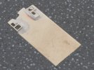
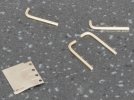
With the steps in place, the next task was to add the prominent "hangers" that the motor bogie is attached to on the real thing. I say "hangers", but they are probably really "supports" as they are used to hold up the motor bogie end of the solebar. Anyway, from a model point of view, a pair hang down from the solebar on each side of the coach around the centre of the motor bogie. I chose to model them from short lengths of 0.5mm nickel silver wire which had a 90 degree bend put in. On the real thing a steel plate forms the top of these hangers which is bolted to the solebar. I found a bit of 0.004" nickel silver sheet, made a few passes of a blade to scribe a four bits 1mm x 2mm wide, then drilled a 0.65 hole in the middle of each. Holes were drilled in the solebar at the relevant positions, and the plate threaded onto the end of the bent wire and wire and plate soldered into position.
49.JPG
The "hangers" that support the underframe above the motor bogie - bent bits of wire and 0.004" sheet represent the plate bolted to the solebar.

Once all four were in place, the motor bogie was reattached, and the bends in the wire adjusted so that the bogie could swivel sufficiently without the outside motion touching the hangers. As it happened, I had made the flipping things a little too long, so files were deployed to remove nearly a mm from the bottom of each one (which resulted in having to re-solder at least 2 of them). Once happy, small 1mm collars were made (I didn't have any 0.5mm ID tube) to represent the ends of the cross rods that run below the motor bogie.

Once everything was in place, the whole assembly (motor bogie, trailing bogie, underframe and body) was temporarily put back together and a couple of snaps taken :
50.JPG

51.JPG

After taking those photos I decided to add the vacuum pipes at each end of the coach (attached to the headstocks), so now it's ready for the paint shops!!

With the Steam Rail Motor nearing completion, I have made a start on my next project :
52.JPG

Thanks for looking.
Ian
 

Ian Smith

Western Thunderer
More Steam Rail Motor progress ...

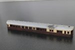
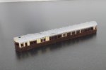
With the body and under frame construction pretty well complete, attention turned to the painting. As usual (for me), the body had received a coat of Halfords etching primer (seen in earlier postings), then everything but the upper half was masked off before the Precision Paints (PP) Coach Cream was applied. After a couple of days to fully harden off, the upper works were coated in a couple of layers of Humbrol Maskol before the lower sides were sprayed PP Coach Brown. Again a couple of days to harden off was allowed before attempting the lining. The black mouldings were ruled on with a Rotring 0.1mm drawing pen (with Rotring black ink). Then the bolections and door drop lights were brush painted with PP Mahogany.

The latter part of the painting process then consisted of an iterative approach whereby any imperfections were touched up with Rotring ink, cream or mahogany as appropriate. As usual, the Rotring ink wasn't too happy to be applied over the PP Coach Brown, so the lower mouldings were brush painted with Humbrol Matt Black, any strays onto the panels was carefully lifted with a fine brush dampened with enamel thinners. In the end, I even had to run a diluted mix of Coach Brown into most of the lower panels as I deemed that the depth of colour wasn't dense enough in places. I sometimes wonder if spraying the whole thing black then painting the panels with a few dilute coats would be a better way forward as the painting of this coach seemed to take forever!!

Anyway, here are a couple of photos of the current state of play :
55.JPG

56.JPG
Looking at these digital images on screen, I might attack the lower panels again with another dilute coat of Coach Brown!! Also in evidence is the near disaster I had with the ink when doing the upper mouldings - a spillage occurred on the roof, although luckily it missed the sides!! Not a problem as the roof still needs to be painted but that will be after transfers and a coat of sealing varnish has been applied.

Thoughts then turned to the coach interior, so a piece of 0.015" plasticard was cut for the floor (with cutouts to clear the busbars and wires that allow pick up from the non-motor bogie). Further 0.015" was deployed for the compartment partitions, and finally seats were built up from 3 laminations of 0.030" with a 0.015" back rest.
53.JPG

54.JPG
Interior in position on the underframe. As can be seen the motor bogie upper works (gear box and motor) have had a coat of matt black to disguise them a little.

A couple of photos of the body plonked onto the underframe :
58.JPG

57.JPG

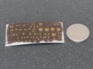
As no transfers are available for a 2mm scale Steam Rail Motor in early livery (Fox do some for Autocoaches), I have had a go at making some myself. Because Modbury is set in 1906, I wanted to model an early example of a Diagram O Steam Rail Motor (the Worsley Works coach being ostensibly the preserved No. 93 of the Diagram R of 1908), so I have chosen No. 61 which was built in March 1906. When outshopped, these early coaches carried a monogram referred to as the Prize Winning Monogram, as a result of a competition held in 1905.

A patch of decal film was painted Coach Brown, then the monograms and numbers were drawn on with Yellow Ochre acrylic ink again in a Rotring pen (0.25mm nib for monogram and 0.1mm nib for the numerals). I did try brush painting it all first with acrylic paint but gave up and resorted to a pen and ink. Hopefully, I have made the numerals small enough to fir in the waist panels, but I'm quite pleased with the way the monograms have worked (they are about 3mm tall) and could possibly have been a little narrower. I will test one of the worse ones in water to make sure that the ink is ok (it should be being acrylic), but I won't try using any of the decal fixers or softeners. If there are any problems I'll give them a coat of varnish before using them.
52.JPG
The monogram and numeral transfers.

Hopefully, I'll just about get her finished in time for the 2mm Association 60 (+2) years anniversary event on the 18th/19th June. Although Modbury isn't in attendance, the Midland Area Group will be there with St Ruth, and there are a couple of other analogue layouts in attendance that she might visit too!!

Thanks for looking.
Ian
 

Ian Smith

Western Thunderer
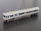
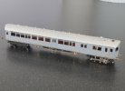
More progress on the Steam Rail Motor - it's completely finished !!!!!

Since the last instalment, the interior has been painted. A lightish brown for everything, then to the seats ... I've had to have a stab in the dark at the actual colours (despite reading the section, well table, in Great Western Way. I've gone with brown in the Smoking compartment as I suspect that they may have been leather, and red (rep) in the other compartment. The whole coach was 3rd class, so it may have all been the same colour/material. I couldn't find anything in the Steam Rail Motors book either.

59.JPG
The completed interior. As the windows are a little bigger than in my other stock I've decided to populate this one. The figures are all Andrew Stadden, and since they're not overly visible I didn't spend a lot of time painting them just splashes of colour really.

With the coach body painted, it was time to put the transfers on. The Prize Monogram transfers that I'd done came out reasonably well so I used those, similarly the "No" for the number (although they were a little oversize). The "6"'s though were in my opinion cr*p, so I decided to use Fox numerals in Yellow for brown stock. The colour is slightly different to the Yellow Ochre ink that I'd used for my home-made transfers, but I decided that I couldn't improve on the dodgy ones I'd done. Once all of the transfers were applied, they were sealed with a spray of Precision Paints Satin Varnish. Once dry, the glazing was added using the Cobex glazing available from the Association. The end windows were cut to size as a single unit, scored where the upright mouldings/window frames are then bent to shape. The main compartment windows once cut to size had the top mm or two sanded to represent the hammered glass in the toplights. All of the glazing was secured with Canopy Glue.

Once everything had thoroughly dried the roof was brush painted in a Precision Paints Dirty Black / Humbrol White mix. After the body and under frame were united (with the interior trapped inside), the handrails for the retractable steps were bent up from 0.010" guitar string. The top bend of the wires locating in holes drilled either side of the vestibule doors, and the bottom superglued against the side of the middle step (I still need to give these a touch of matt black where they're glued on).

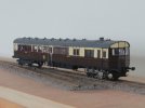
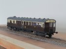
Anyway, here she is finished (apart from the touch up just mentioned) :

60.JPG
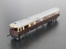
The motor bogie end.

61.JPG
The trailing end.

62.JPG
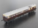
Broadside view of the right hand side.

63.JPG
Broadside view of the left hand side.

Thanks for looking.
Ian
 

Dog Star

Western Thunderer
The GWS Steam Railmotor has been finished in "White Star" moquette which was woven by Holdsworth (I believe). This pattern is chocolate brown with white star "symbols". I understand from discussions with Pete Speller of GWS that the White Star pattern is circa 1905-6.
 

Ian Smith

Western Thunderer
With the Steam Rail Motor now out of the way, I decided to resurrect/start (and finish) some wagon projects. I only had 35 wagons of which 4 were Brake Vans, and since my longest train could be 10 wagons (incl. Brake Van) I really need quite a few more!

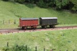
Some time ago, I made up a pair of Iron Mink vans. These were 3D prints courtesy of Richard Brummitt. I had built them but hadn't got round to painting them, so as a "quicky" they had to be done first. I painted one in GWR Red and the other in GWR Dark Grey. Richard had sent me one with a long bonnet and one with a short, checking the HMRS volume on Iron Minks I've made the short bonnet one Red and the long bonnet one Grey.

The lettering on the Red one is Fox transfers (although annoyingly their sheets don't include the "To Carry" wording that would normally go in front of the "x Tons" branding). Therefore I have had to omit the "To Carry" as I've had to on pretty well all of my wagons, although in this case there almost certainly wouldn't have been room between the vertical strapping for it to fit anyway!

For the Grey one, I've decided to fit "cast plates" carrying the number and "G.W.R". There is some debate as to whether the cast plates were fitted to Red wagons or Grey. Long ago, I put my stake in the ground and decided that any cast plate wagons on Modbury would be Grey. My "argument" (NOT proof) for this is quite simply that some wagons retained their plates when re-lettered with 25" GW circa 1904 (when general opinion agrees that the wagons would be Grey). Additionally, one of the wagons that we have photographic evidence of in that guise (25" GW with cast plate numbers) is an Iron Mink, and there is a mis-matched colour patch on the body side where the "G.W.R" plate was, I can't believe that the Great Western would have allowed the wagon to return to service with a small Red patch on an otherwise Grey wagon, but can believe that it was Grey so the painters left it (albeit a slightly different shade that perhaps the photographic emulsion made more contrasty).

Anyway, here are the two Iron Mink vans :
IMG_4565.JPG
The "cast plates" were made by painting a piece of 0.005" plasticard in Humbrol Dark Grey (no. 67 - the colour I use for my grey wagons). The lettering and numbering was then scratched off with a sharp needle in a pin vice to reveal the white of the plasticard , and the plate cut out around the writing. Comparing the two wagons I need to put a bit of rust on the Red one as in theory the livery is older than the grey one!

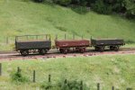
In addition to the vans, I've also added some Opens too. A pair of 4 plank Opens and a 5 plank Open with sheet rail. The basis of all three is the Association body kit(s) for the 4 plank O5 and 5 plank O3. The 4 plankers were made up and stuck on some Association underframes. The 5 plank O3 received a bit of surgery to convert it to an earlier diagram O4. This required slicing/sanding off some of the top plank to make it the same size as the other 4 planks. The diagonal strapping was scraped off and reinstated with 0.005" plastic strip, and the vertical stanchions either side of the doors were reduced to flat strapping . Obviously, the sheet bar had to be fabricated too. Once again, these have been finished in the pre-1904 liveries of Red with painted lettering or Grey with cast plates :
IMG_4564.JPG
I might re-visit the O4 5 planker, and put some Archer's rivet transfers on the diagonal strapping as looking at it now I feel it is noticeable by it's absence!

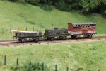
Finally, I've added another Cattle Wagon to diagram W1 (this time with flat diagonal strapping), and in Red livery, and added a load of planks to another 4 planker that was previously made. Additionally, at the 2mm Association Diamond Jubilee event, Kevin Knight kindly gave me one of the Tar Wagon bodies that the Australian contingent produced a couple of years ago. A suitable underframe was built up and stuck under it, a little locking handle was filed up from a small piece of 0.010" nickel silver and stuck on the tank filler. Once painted black, the Wm. Butler transfers that Kevin also supplied were applied. Unfortunately, when I came to dirty the wagon, it seems that the enamel thinners that I was using attacked the decals!! It had been my intention to build up a degree of dirt by applying thin washes of colour. The result was that I had to reinstate some of the lettering with white enamel and a fine brush and then make it even dirtier than I had intended to hide the damage!! Anyway, it does make a nice addition to the stock being a privately owned wagon (and not an Open coal wagon) :
IMG_4566.JPG

So now I have 42 wagons, and am almost ready to take Modbury to RailWells in mid-August!!

Thanks for looking
Ian
 
Top