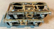
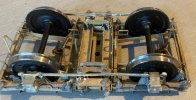
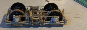
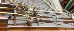
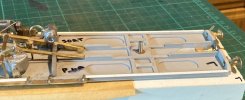
7mm OzzyO is back building a Dave Parkins' kit (and some JLTRT Coaches as well). Now on to some MMP 16ton wagon kits.

OzzyO

Western Thunderer
Hello all,

I set to and drilled all of the axle boxes 2.5mm (if my idea didn't work I could open them out to 2.6mm) .
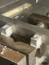
This is how I set the boxes up in the vice two at a time, I'm using a length of 5/16" tool steel to make sure that they are square to the vice.
Bogie 014.JPG

Then a length of 1/4" tool steel across the top of them as well to keep then down on the small lip and then nip up the vice.
Bogie 015.JPG

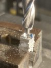
Then it was onto counterboring two axle boxes to prove proof of concept. Keep your fingers away from the side of the counter boreing tool as it take a chunk of flesh from you finger.
Before.
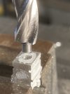
Bogie 016.JPG

After.
Bogie 017.JPG

Brass bearing loose fitted. Has anyone tried using just the white metal as the bearings? It's used a lot in the big world as a bearing material but with a lot of oil.
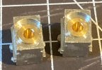
Bogie 018.JPG

The trial fit in one of the bogies.
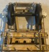
Bogie 019.JPG

Bogie 020.JPG

Bogie 021.JPG

The wheel set spins OK I'm not feeling any resistance that I could put down to the wheel bosses rubbing on the axle box, but I may just take a scrape off the sharp corners of the counterbore just to make sure.

ATB

OzzyO.

PS. now to go and thread some more chairs on rail and get them stuck down.
 

OzzyO

Western Thunderer
Hello all,

I forgot to mention in my last post that the axles have a slight taper towards the centre going from approx. .135" at the out side to .125" at the centre. So I'm not sure how to fit the dynamo wheel onto the axle.
Any ideas on the back of a white fiver to me please.

ATB

OzzyO.
 

markjj

Western Thunderer
Hello all,

I forgot to mention in my last post that the axles have a slight taper towards the centre going from approx. .135" at the out side to .125" at the centre. So I'm not sure how to fit the dynamo wheel onto the axle.
Any ideas on the back of a white fiver to me please.

ATB

OzzyO.
If it's too loose use a piece of heatshrink tubing on the axle then glue the dynamo wheel on it. Paint or varnish might hold it in place if not a bit of super glue. The wheel is only cosmetic and not functional after all. If it's too tight over the heatshrink just open up the wheel slightly to suit.
Sorry I dont have any white fivers.......

Mark J
 

OzzyO

Western Thunderer
Hello all,

I'm not sure about the ideas about the dynamo pulley on the axle, I will have to think on this one.

But I did think about this one and came up with this. The idea is that it will work for both the old JLTRT kits and the DJP kits for both bogie centres.

The first thing that I sourced were these, from flea bay.
IMG_4318.JPG

Then it was getting a bit of shelf board cut to size with a couple of cuts in it,
Then drill some holes in it at the bogie centres for both JLTRT and DJP ( one is approx. 6mm and the other 6BA {M3?].
Also remembering to do them both at 40' and 46' 6" centres.
IMG_4319.JPGIMG_4320.JPG

Seeing how the basic under frame looks on the bit of plank.
IMG_4321.JPG

Showing the two length of under frame.
IMG_4322.JPG

Then you get all three of them, a bit like busses none for an age then they all turn up
IMG_4323.JPG

Just got to make some small clamps for the DJP underframes and the job should be a good un.
All the best

OzzyO.
 

OzzyO

Western Thunderer
Hello all,

apart from working on the track for Lochmaben I have been doing some work on for the BGs and Pos, with the chance of some more of them in the future. so I thought that it could be a good idea to make some jigs and this is what followed.

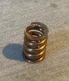
The first is a spring compression tool as I think that the coils on the springs supplied are a bit too open. Full size about 63mm.
Bogie 022.JPG

After the tool about 44mm.Bogie 024.JPG

The next one is a holder for cutting the spring to length this also checks that I have remembered to trim the end of the face square.
Bogie 025.JPG

In use getting ready to cut the spring off. Then it's grinding the spring to length.
Bogie 026.JPG

After using the tools this is what I'm left with.
Bogie 027.JPG

Then after a bit more of a clean up.
Bogie 028.JPG

I did think that it was worth it as I've got 80 Bolster springs to make. I'm not sure what the springs are made of but I think that it could be phos. bronze.

ATB

OzzyO.
 

OzzyO

Western Thunderer
Hello all,

after what seems an age (well it is) I went into the workshop. The first job was to reconnect the grit blaster and fill with grit.
Then the problems started first I had no lights working in the cabinet, (cheap LED strip lights, I'm looking at some new lights not cheap but should be better).
Then I powered up the compressor only for it to not cut off below full pressure and the safety valve went off. So I only got a bit of the job that I wanted to do done.

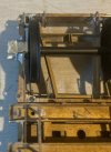
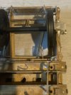
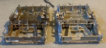
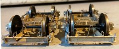
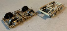
After the bogies had been stood for ??? months' time had taken its toll on them. The one that I did get to clean up on the right in all of the photos, I think.
Bogie 030.JPG
Bogie 031.JPG
Bogie 032.JPG

I may look at getting one of them on its wheels in the next week or so, but Lochmaben is eating up quite a bit of time and we also have our show on the 8th and 9th of October.

ATB

OzzyO.
 

OzzyO

Western Thunderer
Hello all,

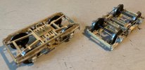
I got back into the workshop yesterday and had a bit more of a play. Compressor still playing up, but I've found a bit of a way around it. So, it was grit blast the second bogie, the same end of the two bogies that are in the last photo of the last post.
Bogie 32 a.JPG

I did look at spring them using the way that D.J.P. (MMP) has in the kit. But "I" could not get on with it!
So, it was out with the Slater's horn block coil springs, the top of the axle box had been drilled out for the pegs on the dummy leaf springs, so it was just a matter of opening up the holes a bit. You can just see the springs in this photo.
Bogie 035.JPG

The bogie on the left is not as dirty as it looks in the photos. I did a spring load test on the bogies and for full depression it works out at approx. 4.5oz. These bogies are for under a J.L.T.R.T. POS I'm still expecting this to depress the spring to their full limit. When I come to build the bogies for the MMP BGs I'm going to look at some stronger springs. That is if I have enough of them.
Bogie 033.JPGBogie 034.JPG

Then I found them like this! I wonder if I'm going to get some baby bogies???
Bogie 036.JPG

ATB

OzzyO.
 
Last edited:

OzzyO

Western Thunderer
Now I'm sort of back at it, I've just thought what dia. the brake pull rods are? I'm thinking about between 3/4" (0.5mm) & 1 1/4" (0.7mm). If anyone can help it would be much appreciated.

ATB

OzzyO.
 

OzzyO

Western Thunderer
As no one replied to my last question about the brake gear pull / push rods I decided to go for 0.5mm (3/4").

The first cross yoke going in place, I'm not so happy with some of the parts. But more on that later.
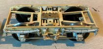
Bogie 037.JPG

The bogie just about complete just some bits to sort out and check for any shorts. The brake pull rod is in place for fitting to the coach underframe.
Bogie 038.JPG
Bogie 039.JPG

Then from above.
Bogie 040.JPG

I have started on the coach underframe that theses bogies are going to fit on, it's a J.L.T.R.T. Post office sorting van (POS). The one that I'm looking at modelling is M80300 or 1. The kit is correct for both of them, I'll be doing it with no net or pick up gear as that is out of our time frame. I'm not going to show you what you get in the box as I think that Brian Daniels has already done that, some of the photos of the parts Will be by Brian and some by me. If the photos are by Brian, I'll Add B.D.

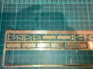
Some of the etches that you get, the one that I'm looking at the moment is the top one (BD). The parts are the bottom two of the top etch.
TPO 3.jpg

But before I get on to fitting them, I'll go back a bit.
I was going to fit Kadee's to all of the kit-built coaches and milled out all of the J.L.T.R.T. floor pans to suit, then Ellis Clark drops the bomb shell, drop, head buck-eye couplings in 7mm.
To sort the 'new' gap in the buffer beam, this is what I did. A bit of 6 x 6 L angle and some brass to get it to the same hight as the buffer beam. I also added some flat headed rivets to aid to the shear strength of the buffer beam. Then it was counter bored for the fixing hole for the body bolts.
Floor 001.JPG

I'm thinking that these kits maybe some of the first that J.L.T.R.T. produced as one of the etches is dated 2003 and it's also using white metal for the angle truss supports.

I don't know what grade of brass was used for the etches but I could not bend it in my bending bars after drawing the etched line to show on the outside. So, it was out with the small and larger hammers, until I was happy. Then I got this.
Floor 002.JPG

ATB

OzzyO.
 

Attachments

  • IMG_8281.JPG
    IMG_8281.JPG
    303.7 KB · Views: 3
Last edited:

OzzyO

Western Thunderer
Does anyone know who makes the following roof vents in 7mm.
Shell roof vent,
Scallop roof vent.

Thanks for any help,

OzzyO.
 

dibateg

Western Thunderer
Sidelines do the shells in brass.

Scallops, the BR ones? - maybe Dave Parkins? Not sure if he sells 'em seperately.

Cheers
Tony
 

djparkins

Western Thunderer
Does anyone know who makes the following roof vents in 7mm.
Shell roof vent,
Scallop roof vent.

Thanks for any help,

OzzyO.
Araid we don't see vents seperately from our MMP stuff but we might have something in the Cavalier range -

David J Parkins - might be something in the LMS section.

Could I request a change in the title to this thread?

David Parkins
 

OzzyO

Western Thunderer
Hello all,

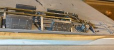
more work has been done on the floor/underframe of the POS, as far as I can tell from photos the battery boxes were asymmetrical, but finding a good side on view is well???
Floor 004.JPGFloor 005.JPG
Floor 006.JPG

A few more bits to add. These are the dynamos that I'm going to use from D.J. Parkin
IMG_8336.JPG

And in place. Some wires to add and a few more bits.
Floor 007.JPG

Getting ready for the drophead buckeye couplings, I thought that I may not have enough clearance for the spring, so I milled a slot in the brass work.
Floor 008.JPG

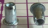
Buffer bodies also in place, then it's vac and steam pipes followed by the E.T.H. gear. I'm having to replace the brass inserts for the bogies as they are for 4mm screws and the D.J. Parkin ones that I'm going to use on this coach use 3mm ones.
Floor 009.JPG

While all of the above was going on I have been filling in parts on the body that I don't require i.e., the lamps and the toilet window. I couln't find my filler so I used super glue jell to do the job, seems to be working OK.
Body 001.JPG
Body 002.JPG
Body 003.JPG

ATB

OzzyO.
 

OzzyO

Western Thunderer
Hello all,

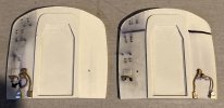
a bit more work on the body, until I got attacked by a porcupine and it did this to the ends of the POS, so work stopped.
Body 004.JPG

After I'd had a go with a pair of cutters to snip them off and all I got was dints in the cutters, it was out with the Dremel and cutting disc, to produce this.
Body 005.JPG

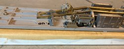
Then back onto the floor, the first job was the running boards (the ones in the kit look to have been drawn for the POS when it had the pick-up gear and the set down gear), so it was make some and cut down others to suit. Then I decided to add the wires from the dynamos, I was looking at a photo that was the right way up and well you can see what I have done.
Floor 010.JPG

But it's starting to look nice and full under the floor.
Floor 011.JPG

Onto the couplings, I'm going to use the Ellis Clark drophead buckeye couplings on this coach along with the rest of the coaches that will make up this rake. That will be four BGs (brake gangway) from D. J. Parkin (MMP). But I also want to use his draw gear set-up as shown below. So, I could end up wrecking a good coupling to find out that it can't be done.
We will see.
IMG_8350.JPG

ATB from a sunny but cool Barrow,

OzzyO.
 

OzzyO

Western Thunderer
Hello all,

I went to start finishing the ends off but only four lighting? connectors the POS has four at each end as do a lot of Post Office only vehicles, so it's looking like a bit of scratch building is in order. Just a bit of turning, milling, filling & drilling. What can go wrong? All of the cast ones are on one side and the scratch built ones on the not normally viewing side.
Body 006.JPG

Then it was back onto the floor. This is why I don't normally take photos on my workbench.
Floor 012 - Copy.JPG

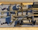
Dynamo wires sorted out, then it was applying some plasicard strips to the bottom of the floor pan to represent the bottom solebar channel, I've used 15 thou thick but 10 would have been better.
Floor 012.JPG

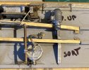
A view of the sorting side with the strips in place.
Floor 013.JPG

The pick-up side of the floor (stop sniggering at the back of the class).
Floor 014.JPG

A close up of one end of the pickup side and one showing the full length.
Floor 015.JPG
Floor 016.JPG

Then one from the top, I do think it looks better for the work, I may have to do a bit of trimming at the L/H end as it looks a bit further out than the rest.
Floor 017.JPG

Then it was onto the ends to fit the vac. and steam heat pipes. Just got to get the E.T.H. gear and a few more bits and the job should be a good un. The long screws that you can see are the hold the roof down, the kit comes with cheese head screws that I think may catch on the wheel flanges.

Floor 018.JPG

ATB

OzzyO.
 
Top