Rivermead Central

Yorkshire Dave

Western Thunderer
In respect of the paint colours not only the age, exposure and varnish affect the finish and colour over the years, the original pigments used and stability can also play a part.

In addition the paint batch would have been hand mixed which we know can vary. Being hand mixed the mixer's ratio measurement may not have been precise to the nearest gram or ounce as specified. Again leading to subtle variations.
 

Masbury

Member
I wonder whether some one could help me with enquiries about clockwork controlled locomotives, such as the Walker-Riemsdyk (or Riemsdijk) 0-6-0 tank engines which Martin is planning to use on the incline between the upper and lower levels of the Rivermead Central layout, please?

1. Does the setting of the variable speed control disc affect the length of run? I would surmise that it does not: the gear train between the mainspring and the driving axle is not itself variable, and a given number of turns of the key would, it would appear, result in a corresponding number of turns of the driving axle, irrespective of the rate at which the spring is released.

2. Does the setting of the variable speed control affect the power output of the engine? Insofar as the control restrains by friction the release of the spring it would seem that setting a slow speed might reduce the output at the drawbar. But I may be mistaken about the physics/mechanics of these engines!

As it happens, I do possess one of the W-R engines. At present, operating the control disc seems to make little difference to the speed of the engine, but it may require just a simple adjustment.

A 1955 Walkers and Holtzapffel catalogue states (on page 35) that the engine was available in two versions: the 'standard' (100/110 feet run) 'for general service'; and a 'gradient type' (80/90 feet run) 'for heavy haulage'. Presumably this difference was achieved by alterations of the ratios between some of the gears in the train.

John
 

40057

Western Thunderer
I wonder whether some one could help me with enquiries about clockwork controlled locomotives, such as the Walker-Riemsdyk (or Riemsdijk) 0-6-0 tank engines which Martin is planning to use on the incline between the upper and lower levels of the Rivermead Central layout, please?

1. Does the setting of the variable speed control disc affect the length of run? I would surmise that it does not: the gear train between the mainspring and the driving axle is not itself variable, and a given number of turns of the key would, it would appear, result in a corresponding number of turns of the driving axle, irrespective of the rate at which the spring is released.

Very little, if at all. The residual power in the spring probably does become insufficient to move the loco/train slightly ‘earlier’ in the unwinding process when the loco is set at a slower speed.

2. Does the setting of the variable speed control affect the power output of the engine? Insofar as the control restrains by friction the release of the spring it would seem that setting a slow speed might reduce the output at the drawbar. But I may be mistaken about the physics/mechanics of these engines!

Yes, but not by that much. The loco will still pull a reasonable load at quite a slow speed, but it will pull more if the speed is set higher.

As it happens, I do possess one of the W-R engines. At present, operating the control disc seems to make little difference to the speed of the engine, but it may require just a simple adjustment.

The speed control is also the brake. When turned right down, the engine shouldn’t move even if fully wound. As the control wheel is turned, the loco should run progressively more quickly. I haven’t come across the problem you describe in the 0 gauge 0-6-0 tanks. I do have a rather larger van Riemsdijk motor which is very powerful. It’s just a motor sold for scratch builders. On test, the speed control on that motor won’t hold it stationary against the spring if fully wound. Built into a locomotive, maybe the extra friction/weight would make the speed control into an effective brake. So really, another clockwork scratch build is required to use this excellent and powerful motor …

A 1955 Walkers and Holtzapffel catalogue states (on page 35) that the engine was available in two versions: the 'standard' (100/110 feet run) 'for general service'; and a 'gradient type' (80/90 feet run) 'for heavy haulage'. Presumably this difference was achieved by alterations of the ratios between some of the gears in the train.

John

I have never found a loco I was convinced was the ‘gradient type’. However, I have seen versions of the 0-6-0 with larger diameter driving wheels. So perhaps these were the ‘standard models’ and the versions I have (with 5’ diameter drivers) are actually the gradient version.

If I found a loco or mech with a different gear train, that would give a definitive answer. But the difference described would be produced by different wheel diameters, which there certainly are.

Martin

P.S. I refer you to Tom Mallard’s work bench thread where he is working on one of these motors currently.
 

Masbury

Member
Martin
.
Thank you for your comprehensive and very interesting - and prompt! - reply. I am now much clearer about this mechanism and its characteristics, and I can also see that the different performances of the standard and gradient versions could be achieved by varying the diameter of the wheels. This would be much simpler than process which I had imagined - viz. the provision of different gear trains.

The diameter of the wheels of my engine is 1 1/4" - equating to about 4' 6" in full size. On one winding, the engine runs for about 60 feet on - mainly straight - Maldon track. This might be improved when the engine is properly lubricated and adjusted, but I think that what I have may be the gradient version?

I am now about to visit Tom Mallard's work bench thread.

John
 

40057

Western Thunderer
Martin
.
Thank you for your comprehensive and very interesting - and prompt! - reply. I am now much clearer about this mechanism and its characteristics, and I can also see that the different performances of the standard and gradient versions could be achieved by varying the diameter of the wheels. This would be much simpler than process which I had imagined - viz. the provision of different gear trains.

The diameter of the wheels of my engine is 1 1/4" - equating to about 4' 6" in full size. On one winding, the engine runs for about 60 feet on - mainly straight - Maldon track. This might be improved when the engine is properly lubricated and adjusted, but I think that what I have may be the gradient version?

I am now about to visit Tom Mallard's work bench thread.

John
Hi John

The wheels are on the small size. Maybe you actually do have an example of the elusive gradient model.

Can you show us a photo?

Martin
 

40057

Western Thunderer
Inching further southwards with the wall covering along the west wall of the room:

FB5B0562-44E8-4097-BCE0-624AE1D0951F.jpeg

I still have to apply the grey base-board paint over the countersunk screws holding the short length of wall in place.

Now, experiments to disguise the battens under the sleepers and height of the track. I can see a need in specific and limited locations to have the ‘ground level’ adjacent to the track at least level with the top of the battens. Stage one is to fasten a length of strip wood roughly the same height as the battens under the ends of the sleepers. I have done this here, between the broader sleepers with the point levers:

EE6CE278-6157-443B-A544-C9CF6ED138AC.jpeg

I don’t think it’s a dramatic improvement, appearance-wise. But it does avoid the ‘levitating sleeper’ look visible on the other side of each point lever.

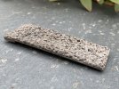
I shall continue this experiment by adding ballast to the same short length of track. I have cut out rectangles of 2 mm ply the same size as each of the gaps between the sleepers. These are to be covered with Green Scene ground-up fruit-stone ‘ballast’:

A3EA09D9-2E5B-478D-A408-9484F5EE89D1.jpeg

I’ll need to add some ballast-coloured paint.

I’m really not sure how this is going to look. The ‘ballast plates’ won’t be fastened down so if I don’t like the appearance, I can just remove them. There is no particular need for a higher ground level or ballast in the location being used for the experiment. I chose this piece of track because it was a short length between the two broader point-lever sleepers, which provide ‘ends’ to the differently treated section.

Martin
 

John R Smith

Western Thunderer
Now, experiments to disguise the battens under the sleepers and height of the track. I can see a need in specific and limited locations to have the ‘ground level’ adjacent to the track at least level with the top of the battens. Stage one is to fasten a length of strip wood roughly the same height as the battens under the ends of the sleepers. I have done this here, between the broader sleepers with the point levers:

I have already shown you my efforts to disguise the battens with a cork strip, but I have not really thought about anything further in the way of ballast. I can see that there are situations where we perhaps really need to do something about the monstrously high rail top which, to be fair, many famous practioners have managed to live with. Situations like road vehicles loading from wagons in a goods yard, or MPD staff working around engines, for example.

I have come across an interesting example of an early indoor layout which was fully ballasted, the Gauge 2 railway built by H F R Franklin and featured in "Model Railways" for April 1909 -

Franklin 1909 Layout 02.jpg

This layout was powered by live steam, not clockwork or electricity. The charming photograph on the right above (taken by W J Bassett-Lowke) shows Mr Harry Franklin on the left with his brother Albert on the right. As it notes at the bottom of the page, the line was ballasted by granite chips.

John
(this MR scan from "Victorian" over on RMweb)
 

Masbury

Member
Hello Martin,

I shall see if I can provide a photograph - perhaps next week.

Meanwhile, I wonder whether we could have a (partial) reprise about the subject of controlled clockwork.

1. The earliest, and most intelligible, method of altering the speed of clockwork locomotives seems to have been by providing for changes to be made within the gear train. By making changes in the gear ratios, it was (and is) possible to have two speeds, either of which can be selected by the operator before starting the engine. I have a Gauge 1 LNWR 0-6-0 locomotive with this feature: either moderately slow or moderately fast speeds are obtainable au choix. You have indicated (posts 644, passim) that this arrangement was not provided in Gauge 0 locomotives -or at least in engines made by Bing or Bassett-Lowke.

2. Then we have the Walker-Fenn ('W-F') system, which employs parts of a gramophone motor to regulate the speed. This system is highly sensitive, and can be used to run the engine at a very slow but still steady rate. The only disadvantage would appear to be that, since the size of the gramophone parts is non-negotiable, we have to have a quite large engine to accommodate them. The W-F 0 gauge 0-6-0 tank engine known to me resembles a Bowman 0 gauge live steam engine in that it seems to have been made to a scale of 8mm. to the foot, and possibly larger.

3. Now we come to the Walker-Riemsdyk (or Riemsdijk) ('W-R') arrangement, which has already been described in posts above. A 1955 Walkers and Holtzapffel catalogue refers to 'our pre-war controlled Clockwork Locomotives'. These were perhaps W-F locomotives: they are unlikely to have been designed/produced by John van Riemsdijk ('JvR'), who was only 14 years old when WWII began. In some respects the motor of the W-R engine was what might nowadays be called 'sub-optimal': this was not due to any deficiency on the part of JvR, who told my late friend Bill Wilson (a physicist and expert on model locomotives) that the product had been constrained by manufacturing costs - hence the rather flimsy nature of some of the components. It would seem that a decision had been taken that the baseline retail cost of the locomotive must not exceed £5.00, a figure to which must be added purchase tax (then set at 16 2/3%), with the result that the full retail cost to the customer was £5. 16s. 8d. (This equates very roughly to £137 at 2026 prices, but, because of the general, and considerable, rise in real incomes over the past 70 years, the sum of £5. 16s. 8d would for many people have meant more in 1955 than would the still substantial sum of £137 today.)

4. Lastly (for the present) there is the 'Teleguv' revolution, sometimes acclaimed in rapturous terms. Unfortunately (for me), I do not know exactly how this 'Teleguv' works or how it is fitted, or whether it can be incorporated retrospectively in existing mechanisms. I would, if someone could provide it, welcome enlightenment on these points, expecially as the system seems to have been such a 'breakthrough'.

5. Equally, I do not know anything about the operation of the speed control fitted to the B-L large 6 wheel 0 gauge mechanisms such as those fitted to the 'Royal Scot'. Again, an explanation would be much appreciated.

John
 
Last edited:

40057

Western Thunderer
Hello Martin,

I shall see if I can provide a photograph - perhaps next week.

Meanwhile, I wonder whether we could have a (partial) reprise about the subject of controlled clockwork.

There is a lot of previous discussion in this thread, but scattered — sometimes just comments in one post before attention shifted to some other topic.

1. The earliest, and most intelligible, method of altering the speed of clockwork locomotives seems to have been by providing for changes to be made within the gear train. By making changes in the gear ratios, it was (and is) possible to have two speeds, either of which can be selected by the operator before starting the engine. I have a Gauge 1 LNWR 0-6-0 locomotive with this feature: either moderately slow or moderately fast speeds are obtainable au choix. You have indicated (posts 644, passim) that this arrangement was not provided in Gauge 0 locomotives -or at least in engines made by Bing or Bassett-Lowke.

The earliest form of governor (to reduce the speed) was a train. Marklin locomotives in the mid 1890s have no governor in the motor. The train was the governor, and the instructions made clear the entire train supplied in the set had to be used — otherwise the locomotive would fly off the track on the curves.

Nowadays, clockwork trains should be thought of as having two governors — the train and the one in the motor. To some extent these are compensatory; if speed is retarded by a heavy train, the restraint imposed by the governor in the motor will be reduced.

The system of having alternative speeds through alternative gear trains was usual in the larger Gauge 1 and 2 locomotives pre-WW1. As far as I know, this system was never included in any commercially made 0 gauge motors. I guess that was due to the smaller size or perhaps the extra cost was seen as disproportionate for an 0 gauge model. A downside of the alternative gear train system was just the two speeds. On the plus side, all the various other speed control devices mentioned below rely on increased friction to control speed, so some haulage capacity is lost when speed is reduced.

2. Then we have the Walker-Fenn ('W-F') system, which employs parts of a gramophone motor to regulate the speed. This system is highly sensitive, and can be used to run the engine at a very slow but still steady rate. The only disadvantage would appear to be that, since the size of the gramophone parts is non-negotiable, we have to have a quite large engine to accommodate them. The W-F 0 gauge 0-6-0 tank engine known to me resembles a Bowman 0 gauge live steam engine in that it seems to have been made to a scale of 8mm. to the foot, and possibly larger.

Agreed, the locomotives are unrealistically huge. I think the trick is that the friction losses are very low, but the retarding effect is magnified through the gearing.

3. Now we come to the Walker-Riemsdyk (or Riemsdijk) ('W-R') arrangement, which has already been described in posts above. A 1955 Walkers and Holtzapffel catalogue refers to 'our pre-war controlled Clockwork Locomotives'. These were perhaps W-F locomotives: they are unlikely to have been designed/produced by John van Riemsdijk ('JvR'), who was only 14 years old when WWII began. In some respects the motor of the W-R engine was what might nowadays be called 'sub-optimal': this was not due to any deficiency on the part of JvR, who told my late friend Bill Wilson (a physicist and expert on model locomotives) that the product had been constrained by manufacturing costs - hence the rather flimsy nature of some of the components. It would seem that a decision had been taken that the baseline retail cost of the locomotive must not exceed £5.00, a figure to which must be added purchase tax (then set at 16 2/3%), with the result that the full retail cost to the customer was £5. 16s. 8d. (This equates very roughly to £137 at 2026 prices, but, because of the general, and considerable, rise in real incomes over the past 70 years, the sum of £5. 16s. 8d would for many people have meantmore in 1955 than would the still substantial sum of £137 today.)

Undoubtedly, the motors in the Walker-Reimsdyk 0-6-0s are excellent and much better quality than the rather flimsy and basic bodies. The variable speed is produced by moving the rotating bobs of the governor closer to or further from the rubbing plate (which is the motor side frame). I think again this is a ‘low friction’ system that depends on gearing to produce a sufficient retarding effect.

4. Lastly (for the present) there is the 'Teleguv' revolution, sometimes acclaimed in rapturous terms. Unfortunately (for me), I do not know exactly how this 'Teleguv' works or how it is fitted, or whether it can be incorporated retrospectively in existing mechanisms. I would, if someone could provide it, welcome enlightenment on these points, expecially as the system seems to have been such a 'breakthrough'.

The Teleguv — pure dead brilliant. You don’t get variable speed, but you do get a longer run, more haulage capacity and no noise. See posts #987–#997.

5. Equally, I do not know anything about the operation of the speed control fitted to the B-L large 6 wheel 0 gauge mechanisms such as those fitted to the 'Royal Scot'. Again, an explanation would be much appreciated.

The Bassett-Lowke variable speed mechs operate on the same principle as the van Riemsdijk system. In the Bassett-Lowke motors it is the rubbing plate that is moved closer to or further from the rotating bobs. The range of speeds produced is much less than for the van Reimsdijk motors, even the slowest speed still being quite fast. So Bassett-Lowke variable speed mechs still have a separate brake. The friction losses are considerable and haulage capacity, in my experience, is significantly less at slower speeds.

Martin
 
Last edited:

Masbury

Member
Hello Martin,

Thank you for this further edification! I am trawling through the many posts on this thread, and hope to gain further insights into the fascinating realm of clockwork propulsion.

For the present, just one comment, arising from posts 710 et sqq: I do not think that the provision of (only) two coaches in the Hornby 'True to Type' clockwork train sets was a reflection of the haulage capacity of the No. 2 Special 4-4-0 clockwork engines. In my view the decision was made for a marketing reason, that is to say, to keep down the price - in the 1938/1939 catalogue, to £2. 15s. 0d (the electric version with three coaches retailed at £3. 16s. 0d). On another page are details of the No. 2 Special 4-4-2 tank engines and passenger train sets: both the electric and clockwork versions were supplied with (only) two coaches per set. The same applied to the Riviera Blue and to the Metropolitan electric and clockwork sets.

John
 
Last edited:

40057

Western Thunderer
Hello Martin,

Thank you for this further edification! I am trawling through the many posts on this thread, and hope to gain further insights into the fascinating realm of clockwork propulsion.

For the present, just one comment, arising from posts 710 et sqq: I do not think that the provision of (only) two coaches in the Hornby 'True to Type' clockwork train sets was a reflection of the haulage capacity of the No. 2 Special 4-4-0 clockwork engines. In my view the decision was made for a marketing reason, that is to say, to keep down the price - in the 1938/1939 catalogue, to £2. 15s. 0d (the electric version with three coaches retailed at £3. 16s. 0d). On another page are details of the No. 2 Special 4-4-2 tank engines and passenger train sets: both the electric and clockwork versions were supplied with (only) two coaches per set. The same applied to the Riviera Blue and to the Metropolitan electric and clockwork sets.

John
Hi John

The question of haulage capability of clockwork locomotives has come up in this thread more than once.

It’s very difficult to measure because the ‘number of coaches pulled’ will depend on the type and curvature of the track and the weight and wheels of the coaches, as well as the power of the locomotive. The additional uncertainty now is whether present day haulage capacity is less than when the motor was new.

Vintage clockwork locomotives today are routinely run in much closer to ideal conditions than was expected when they were made. For a start, modem ‘vintage style’ or ‘replica’ tracks often have far more generous radii than genuine period tinplate tracks. Running on nickel silver or similar rails will greatly reduce friction relative to round-headed tinplate rails.

A Hornby locomotive would be expected to run on a track temporarily laid on the carpet, very possibly not entirely level. On tinplate rails, round 2’ radius curves hauling coaches with, at best, cast lead alloy wheels. The effort required to move even a two coach train in these conditions is considerable. Can a Hornby 4-4-0 be relied upon to pull three coaches a reasonable distance on the oval of track supplied in sets when laid on the floor? No, not in my experience. There is variation in motor performance, but if even 10% of Hornby 4-4-0s couldn’t pull the coaches supplied in the set, that’s an awful lot of disappointed customers and/or expensive guarantee work replacing motors.

A set with a loco and two coaches was going to work, even if the loco was a below average one. A reliable product.

Do you have a Hornby 4-4-0 that will happily pull three Hornby coaches a good distance in the conditions it was expected to be used?

There seems to be very little contemporary information about haulage capacities of new clockwork locomotives in specified conditions. Statements that a loco would pull ‘four coaches’ are pretty much meaningless without knowing whether that was on straight, level track or round a 2’ radius curve. Whether the track was tinplate or had drawn brass rails. Whether the coaches had alloy or cast iron wheels.

I refer you to post #871. The table therein does include some definitive, contemporary, data on haulage capabilities. Specifically, the pre-WW2 Bassett-Lowke 4-coupled motor is stated to be capable of hauling three B-L coaches fitted with cast iron wheels for 90’ on straight track with drawn rails. This is in line with my personal experience. The implication of this statement is that the motor wouldn’t manage this load on curved track, or on tinplate rails or with coaches with alloy wheels. Which I would also say is correct based on personal experience.

For a Hornby loco to pull three coaches with alloy wheels round 2’ radius curves on tinplate track it would have to have a much stronger motor than the Bassett-Lowke equivalent mechanism. I accept the Hornby coaches are lighter, but the track curvature is the killer in terms of load pulled.

I have not found Hornby no.2 special mechs to be noticeably superior to the standard Bassett-Lowke 4-coupled motor.

Martin
 

John R Smith

Western Thunderer
Hello Martin

I thought that for a change of topic you might like an update on my (recently acquired) Bing for Bassett-Lowke 112 0-4-0 tank engine. I now have it up and running at last, and it is a very endearing little loco. I am very grateful to you for your advice on this model, and for guiding me in its direction! I am a bit aprehensive that you may not approve of one aspect of my refurbishment plan, but here goes anyway.

When a new engine arrives at chez Smith, I always deal with the clockwork motor, wheels and motion first, before any cosmetic work is done. It was soon apparent that the old girl had not been used in many years - the mechanism was stiff, the controls jammed up, but after a good clean up and lots of oil later we had things running in both directions with a functional brake. The controls are still a bit iffy as the reverser sometimes blocks for no apparent reason, so there is some work to do. There is the usual wear on the coupling rods and connecting rod bearings, but nothing too bad. The wheels are as you noted, cast-iron and in very good shape.

On to the cosmetic stuff, then, and the paintwork seems to be original with only the bufferbeams showing evidence of repainting. It is a wonderful colour scheme, with intricate black panelling, Indian Red valence and reverse cornered black and white lining on the side tanks and bunker. There is the usual light surface crazing, or craquelure, but no loose paint. So mostly it was a clean and polish job, shine up the whistle and redo the cab roof with a very light coat of paint. There was one major problem - a previous owner had changed the front buffers and coupling to some rather unbecoming items -

SAS Bing Detail 01.jpg

The buffers were not even a pair, and the coupling was horrible. At the rear, the coupling and the buffers were original -

SAS Bing Detail 02.jpg

And here is where I have strayed from the True Path. I had the correct couplings in stock, but no Bing buffers. And I have to say that I really do not like these little Bing buffers - to me they look cheap, and I don't know why they persisted with them. So, although I know that I shall be pilloried by all true Bing and B-L followers and collectors, I decided to replace all the buffers with Bassett-Lowke 1930s nickel plated brass ones so she had a full set, and I replaced the front coupling with the correct type. Judge for yourself -

Bing 112 01 Web.jpg

In my defence, I am sure that if you had asked B-L back in 1926 for different buffers, they would have been happy to oblige you for a small additional charge. And this is fully reversible - the original holes remain untouched, and the B-L buffers are held in with a 5BA nut at the rear. From this angle, she really does look like a Drummond LSWR engine, with the "skirts" below the smokebox door and a valve chest cover.

Bing 112 02 Web.jpg

I am not too sure quite how we shall make use of this engine at Kingswell Street. She tends, shall we say, to be a bit lively and rather speedy, so perhaps she might best be tamed with a heavy coach and used for local passenger trains. She has plenty of power and will shunt a heavy Exley around through the reverse curves with great enthusiasm. Here, however, she is on a very short pick-up goods -

Bing 112 on Pick-up Goods 01 Web.jpg

You will notice that I have also got the 6-wheel MR brake van into traffic with some general tidying up and a roof repaint. It has been a lot of fun bringing this little loco back to life. And at only 8 inches long, she is just the sort of engine we need on a very small layout like mine.

John

 

40057

Western Thunderer
Hello Martin

I thought that for a change of topic you might like an update on my (recently acquired) Bing for Bassett-Lowke 112 0-4-0 tank engine. I now have it up and running at last, and it is a very endearing little loco. I am very grateful to you for your advice on this model, and for guiding me in its direction! I am a bit aprehensive that you may not approve of one aspect of my refurbishment plan, but here goes anyway.

When a new engine arrives at chez Smith, I always deal with the clockwork motor, wheels and motion first, before any cosmetic work is done. It was soon apparent that the old girl had not been used in many years - the mechanism was stiff, the controls jammed up, but after a good clean up and lots of oil later we had things running in both directions with a functional brake. The controls are still a bit iffy as the reverser sometimes blocks for no apparent reason, so there is some work to do. There is the usual wear on the coupling rods and connecting rod bearings, but nothing too bad. The wheels are as you noted, cast-iron and in very good shape.

On to the cosmetic stuff, then, and the paintwork seems to be original with only the bufferbeams showing evidence of repainting. It is a wonderful colour scheme, with intricate black panelling, Indian Red valence and reverse cornered black and white lining on the side tanks and bunker. There is the usual light surface crazing, or craquelure, but no loose paint. So mostly it was a clean and polish job, shine up the whistle and redo the cab roof with a very light coat of paint. There was one major problem - a previous owner had changed the front buffers and coupling to some rather unbecoming items -

View attachment 269621

The buffers were not even a pair, and the coupling was horrible. At the rear, the coupling and the buffers were original -

View attachment 269622

And here is where I have strayed from the True Path. I had the correct couplings in stock, but no Bing buffers. And I have to say that I really do not like these little Bing buffers - to me they look cheap, and I don't know why they persisted with them. So, although I know that I shall be pilloried by all true Bing and B-L followers and collectors, I decided to replace all the buffers with Bassett-Lowke 1930s nickel plated brass ones so she had a full set, and I replaced the front coupling with the correct type. Judge for yourself -

View attachment 269623

In my defence, I am sure that if you had asked B-L back in 1926 for different buffers, they would have been happy to oblige you for a small additional charge. And this is fully reversible - the original holes remain untouched, and the B-L buffers are held in with a 5BA nut at the rear. From this angle, she really does look like a Drummond LSWR engine, with the "skirts" below the smokebox door and a valve chest cover.

View attachment 269624

I am not too sure quite how we shall make use of this engine at Kingswell Street. She tends, shall we say, to be a bit lively and rather speedy, so perhaps she might best be tamed with a heavy coach and used for local passenger trains. She has plenty of power and will shunt a heavy Exley around through the reverse curves with great enthusiasm. Here, however, she is on a very short pick-up goods -

View attachment 269625

You will notice that I have also got the 6-wheel MR brake van into traffic with some general tidying up and a roof repaint. It has been a lot of fun bringing this little loco back to life. And at only 8 inches long, she is just the sort of engine we need on a very small layout like mine.

John
Hi John

The 112 looks super and the paintwork is in really excellent condition.

I’m not sure the rear buffer beam had been repainted. Just a rather slapdash application of red over the crimson coat below the platform?

You’re right; I would certainly not have removed the original rear buffers. I probably would have put original type buffers back on the front too. But it’s your engine, so your decision.

As you say, the GNR livery is very attractive.

Martin
 

40057

Western Thunderer
I painted my three pieces of ballast covered plywood:

F05F8D6F-1EE5-4550-A589-9376ED31F3B9.jpeg

And have installed them on the layout:

297FE233-099B-43F8-A709-58A99B944343.jpeg

EE22247E-7CEB-462B-BE63-AFEA04EE2A74.jpeg

Am I happy with how this looks? Ish. At first, I thought I must have used 4 mm scale ballast in error; the stones are too small. Then I realised the stones are scale size. The stones look too small because all the other track components are far too big.

The ballast covered plywood strips were just slid into position under the rails and are not fastened down. If I decide I don’t like them, I can just remove them. Meantime, I’ll leave them in place. It doesn’t look right not having ballast around the ends of the sleepers, so I may conclude it’s better not having any ballast at all.

Martin
 

simond

Western Thunderer
Martin,

might an experiment with polymer foam be worthwhile?

It would be easy to cut into shapes that would fit between & around the sleepers, and could be sprayed grey-ish to look ballast-ish. You’d want a fairly coarse texture, and of course, it won’t have the form of actual ballast, but I suspect might do quite well in the “impressionist” approach.

best
Simon
 

40057

Western Thunderer
Martin,

might an experiment with polymer foam be worthwhile?

It would be easy to cut into shapes that would fit between & around the sleepers, and could be sprayed grey-ish to look ballast-ish. You’d want a fairly coarse texture, and of course, it won’t have the form of actual ballast, but I suspect might do quite well in the “impressionist” approach.

best
Simon
Thank you for the suggestion, Simon.

I have absolutely no intention of applying ballast (however represented) generally across the layout.

I might want to add ballast in selected locations where the very over-scale height of the track would be visually problematic. I’m thinking, for example, of situations such as unloading wagons where there would be (scale height) staff adjacent. I would need to raise the ground level next to the track.

I will consider the options and what I have learnt from the experiment. For instance, I would want to use larger granules to represent the stones if I was to do something similar to my first attempt again.

Martin
 

John R Smith

Western Thunderer
The ballast covered plywood strips were just slid into position under the rails and are not fastened down. If I decide I don’t like them, I can just remove them. Meantime, I’ll leave them in place. It doesn’t look right not having ballast around the ends of the sleepers, so I may conclude it’s better not having any ballast at all.

Hello Martin

A bold experiment, and as you say, easily reversible. The big snag, as I see it, is that in yards and sidings generally the ground level was the same as the tops of the sleepers. This was to make life easier for staff like shunters to move around (remembering that shunters regularly had to run in the old days). So to achieve the correct level the ballast as you say should extend beyond the sleeper ends and merge into the surrounding surface.

John
 

Masbury

Member
Hello John (R Smith),

I really liked your piece about your refurbishment of the '112' tank locomotives. The result is most pleasing. I have agreeable memories of the Gauge 1 steam and clockwork versions of this classic model.

Hello Martin,

Thank you for your further, and again very interesting post (#1,111) above. I fully agree that, for the reasons which you set out, statements to the effect that an engine will pull a certain number of coaches lack meaning: there are (too) many factors bearing upon the matter.

Unfortunately I do not have a circle/oval of 2 feet radius tinplate track on which I could test the hauling capacity of a Hornby No. 2 Special locomotive. But we can in any case be sure that the locomotive would have to contend with a lot of friction, as the sets which I have mentioned were supplied with twelve curved rails and (only) two straight rails. With the exception of the 'True to Type' electric set, the standard issue for the sets, whether clockwork or electric, was two (bogie) coaches. I do not think that anyone has suggested that the clockwork engines would haul three such coaches on the track supplied with these sets.

I have considered the Appendix in Ernest Carter's very valuable book, and would add that the Hornby No. 1 tank engine (a development of the M3) has a long length of run, exceeding 160 feet.

John
 

40057

Western Thunderer
Hello Martin

A bold experiment, and as you say, easily reversible. The big snag, as I see it, is that in yards and sidings generally the ground level was the same as the tops of the sleepers. This was to make life easier for staff like shunters to move around (remembering that shunters regularly had to run in the old days). So to achieve the correct level the ballast as you say should extend beyond the sleeper ends and merge into the surrounding surface.

John
Hi John

I am not going to end up with something that is even a vaguely accurate representation of the ground surface in a real railway yard. The question is: is the result of the experiment visually better than the ‘naked’ track. I really don’t have a problem with having the track fully exposed simply fastened down through the battens. It’s how many vintage layouts were. The overall impression, to me, is fine and authentic. But on closer inspection the sleepers, particularly those in turnouts, jutting out into the air about six inches above the ground surface … err, not great. Then put a member of staff by the track, and the rail top is at waist level. So I do, I think, need to do something in some places so I can have some nice posed scenes.

Can I find a way of further developing the experiment, or taking a completely different approach, to produce the appearance of ballasted track — and track sitting in the ground, rather than on it? And do this without resorting to actually embedding the track in ballast, since I neither want permanently fixed ballast, or lots of loose particles and dust. I’m just not sure how or if this is possible.


Hang on a minute, lads — I’ve got a great idea …

Martin
 
Top