Rob Pulham
Western Thunderer
Thanks Mick,
The instructions are a bit silent on that bit - it took some working out which one went to the front in the first place. To be fair it does tell you to just tack solder them, so swapping it over won't be too onerous.
Thanks again.
The instructions are a bit silent on that bit - it took some working out which one went to the front in the first place. To be fair it does tell you to just tack solder them, so swapping it over won't be too onerous.
Thanks again.


 .......nope ? don't tell me it's going to replace the front door bell
 )")
![[IMG]](https://www.gwra.co.uk/uploads/product-images/2022jul/small/485.jpg "[IMG]")

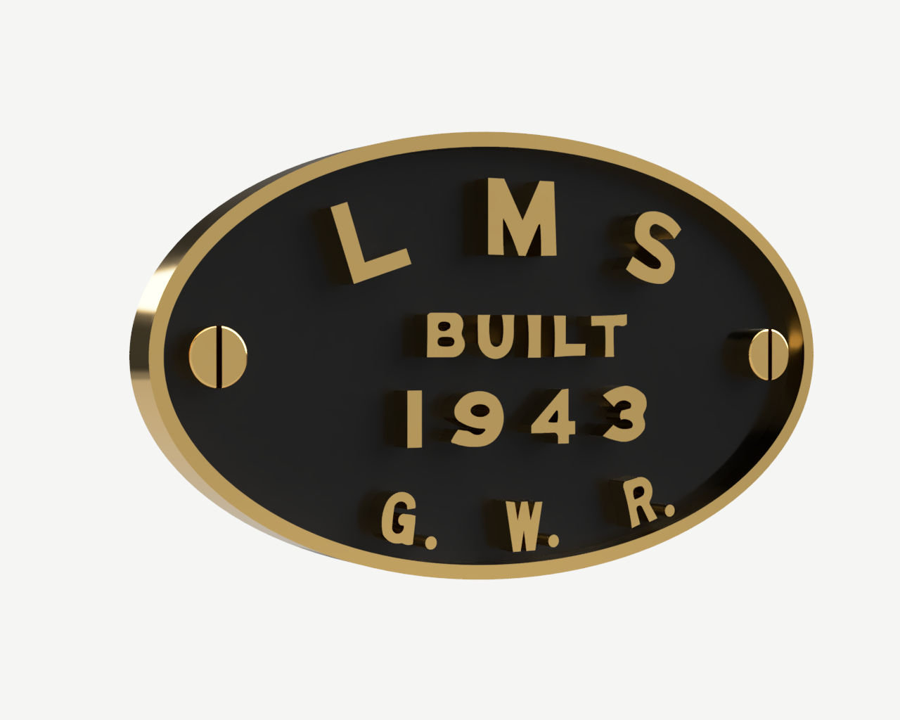

") Great work on the 3D modelling btw!
Great work on the 3D modelling btw!