V2 4 wheel parcel van1/32 and G3

simond

Western Thunderer
Michael,

Mike’s fret is a DC (Dean Churchward) brake, very typical for GW wagons, but not the same as your, or my, vehicle. The triangular frames are also used on coach bogies, usually with a horizontally-pivoted, vertical-ish equalising/operating lever to connect to the other frame, to provide the clasp action. The shoes are hung from the chassis, of course, to react the brake forces.


A Beginner's Guide to GWR wagon brakes (and follow the link)

unfortunately, I haven’t found an equivalent for the earlier Dean brakes

Cheers
Simon
 

michael mott

Western Thunderer
Simon having revisited a number of pictures in the GWR carriage Pictorial book, That has the drawing that I am basically working from, and your model it all seems to tally well. and it makes sense geometrically. Using rods to the outer arms works well. The support posts fixed to the floor of the coach are clearly shown in one of the photos in the book. and finally understanding how the vacuum cylinder works everything appears to make sense.
I spent some time today preparing some brass strip material >.045" x .020" and some .032" x .062" on the table saw, I cut enough to be able to prototype a couple of parts, and I had a bit of rectangular brass tube that I can cut the angled parts from and solder the curved heavier part to the wheel side of the shoe.
I'll have a couple of pictures tomorrow.

Michael
 

michael mott

Western Thunderer
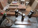
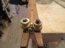
Took a page out of Giles book and did a bit of silver soldering today on the clasp rod clevises.

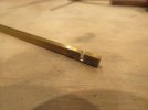
But first the strips cut on the table saw.
IMG_4841x1024.jpg

The smaller size for the hangers for the brake shoes and the larger for the clasp arms. the next shot shows the rectangular tube that I am going to use for the pivot end of the shoes. Filling it with some styrene makes life easier to hold it.

IMG_4842x1024.jpg

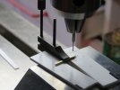
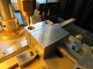
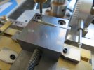
A start was made on the clasp clevises by using some .020" folded over some .032 to get some channel then the cross holes and the rod hole were drilled using a combination of a Lee Valley mini toolmakers clamp and the mill vice. first the cross holes .023" drill. I filled the channel with a bit of scrap .032" and rested the work on some styrene waste supports this way I can see immediately the drill has gone through both sides because a little bit of white swarf shows up.
IMG_4849x1024.jpg

Then switching to the rod hole .032" drill.

IMG_4843x1024.jpg

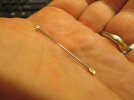
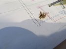
After silver soldering it to the steel rod I did the shaping because it was easy to hold the part once soldered.

IMG_4852x1024.jpg

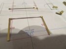
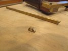
A shot of the arms and hangers rough cut

IMG_4853x1024.jpg

Time to assess the method. Some things just seem to take forever.

Michael
 

Attachments

  • IMG_4845x1024.jpg
    IMG_4845x1024.jpg
    99.7 KB · Views: 3
  • IMG_4848x1024.jpg
    IMG_4848x1024.jpg
    92.1 KB · Views: 2

michael mott

Western Thunderer
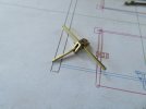
Yesterday I finished drilling all the holes for the clevises, after revisiting the photos of the clevises in the GWR pictorial, I noticed that the clevises were different at each end,one end being longer for either adjustment for wear or a universal length to suit different carriages.
In order to ensure that all the units are the same length I decided to use the third hand which also made sure that the ends were not only the correct distance from each other but also properly aligned. I used the #4 tip on the oxy propane torch.
IMG_4854x1024.jpg

IMG_4855x1024.jpg

them rotated the clamp bar so that i could gently slide off the soldered rod.

IMG_4857x1024.jpg
After shaping and a bit of clean up after the pickle bath.

IMG_4859x1024.jpg

The next task after the rods will be the rocking arms.

IMG_4860x1024.jpg

Michael
 

michael mott

Western Thunderer
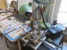
Rocking arms are all drilled also the shoe hangers, Had to break out the micro mill drill that I made a few years ago. It has a 3/32 collet chuck for the constant shank drill bits.
IMG_4874x1024.jpg

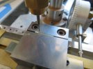
first the rocking arms easy to index to the end of the vice. after both ends were done then the table was indexed to drill the centre holes.

IMG_4868x1024.jpg

Because the vice movable jaw has some allowance to swivel a few thou. I needed to have the short shoe hangers held so that the length crossed the centre line of the vice. A small carriage of some .040" styrene made placing the consistently in the appropriate position and also facilitated removing them easily after they were drilled.
IMG_4871x1024.jpg

IMG_4872x1024.jpg

Now to tackle the shoes.

Michael
 

michael mott

Western Thunderer
This is beginning to feel the same as the wire handles.
Continuing with the prototyping of the brake shoes.

First the filled tube was slotted on the table saw using the zero clearance sled.
IMG_4875x1024.jpg

Next using the jewelers saw the rough shape was cut.

IMG_4876x1024.jpg

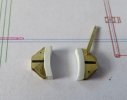
then a folded bit of .015" was silver soldered into the slot in order to form the opening for the rocker arms, I should have silver soldered another piece to narrow the width of where the shoe hanger is fixed, I had to soft solder a bit in later.

IMG_4877x1024.jpg

Then the excess was trimmed off

IMG_4878x1024.jpg

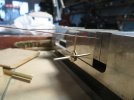
A bit of re-drilling the hanger holes and some pins and it all went together

IMG_4883x1024.jpg
IMG_4881x1024.jpg

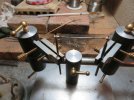
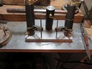
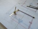
And then connected to the clasp rod.

IMG_4884x1024.jpg

The curved part of the shoe will get soft soldered onto the main body once I get the whole sequence sorted. The pins will be turned down with a head and then a drop of Ac glue will hold them in place. after it is all blackened.

Well that's the plan at the moment, but things could change.

Michael
 

Mikemill

Western Thunderer
Michael

I am impressed with your versatile holding jig for soldering also the pillar drill with fine positioning devices, is that a bought item of did you make it?

I find it interesting how different people approach a task, on the flat bar with a hole at either end I would have drilled the holes in a larger piece of metal and used buttons to guide cutting out the bar! That is what make this hobby so interesting.

Good job on the brake gear


Mike
 

michael mott

Western Thunderer
Good afternoon Mike, The small pillar drill I made especially for doing these small jobs, one thing that would have made the pillar drill easier to control the vertical large movement would have been to add a lead-screw of some sort to wind the whole head up and down. the quill works with a rack and pinion. the motor was a 9v surplus from a local supplier.

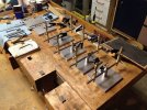
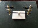
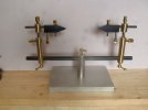
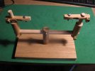
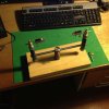
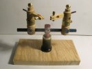
My universal holding jig came out of a frustration with the small commercial ones that have a sort of simple ball joint and crocodile clips. my holding device was made from some salvaged 1 inch duraluminium bar from a display. I went on to develop a more streamlined one from brass and steel. I made 13 sets of these a few years ago. I sold them to the model shipbuilding community around the world. some had spring holders and also the toolmakers type clamps. In the end i decided that doing production type work was better left to others.
IMG_1561x1024.jpg

IMG_1842x1024.jpg
IMG_8541x1024.jpg
and a wooden one, using 1/2 inch dowels for glue work
IMG_8436x800.jpg
and one from salvaged tripod legs
IMG_1413x1024.jpg
A boxwood and ebony version
IMG_8463x1024.jpg

I find that because we end up having to hold all sorts of different things to solder or glue that it becomes a nice departure to figure out a way that is repeatable for the next time. And this tool does it for me.

I have some drawings somewhere that I did I can find them and post them if anyone is interested. This stuff should probably be in the workshop and Techniques area.

Thanks for the compliment on the brake gear.
And like yourself it is one of the things that I enjoy about the forum is learning about how others solve the making of parts for their models. on larger parts I use filing buttons, but these small bars are only 1/16th wide so a few stroke with a 400 grit sanding stick does the trick.

Michael
 

michael mott

Western Thunderer
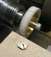
Continuing on with the brake shoes I made a sanding drum just a hair larger than the wheel treads. A flywheel that I did not use for the Victorian experimental loco was the donor, chucked it up in a 3/16 Morse collet with a 10x24 cap head screw and ran the drum on the slowest speed in back-gear on the Myford lathe, I clamped a bit of 1/4 inch thick maple into one of the quick change tool holders to act as the table.

capture4895.jpg
Holding the shoe between my finger and thumb was able to sand the shape of the front of the shoe from a bit of rectangular styrene that was glued to the flat part of the brass shoe. a bit of 5 thou styrene cut with a knife was then glued with some MEK to hide the joint.

capture4896.jpg

Once it is painted nobody will know that it is styrene and brass, except anyone who reads this;)

Michael
 

Richard Gawler

Western Thunderer
Please, do a have a preferred glue for attaching styrene to brass, and do you prepare the brass e.g. roughen the surface beforehand? I was intending use some styrene on a brass loco to make for thicker buffer beams but settled on obechi because I knew I could use Evo-Stick to make it hold.
 

AJC

Western Thunderer
Mike,

I love the work on the brakegear (an the clamps - very elegant).

Please, do a have a preferred glue for attaching styrene to brass, and do you prepare the brass e.g. roughen the surface beforehand? I was intending use some styrene on a brass loco to make for thicker buffer beams but settled on obechi because I knew I could use Evo-Stick to make it hold.

That's an interesting question more generally. My answer is that 'it depends'. When I do this, I try to incorporate some sort of mechanical fixing or anchor in order that the glue isn't doing all the work, but in general, superglue for small things, five-minute epoxy for larger ones.

Adam
 

Richard Gawler

Western Thunderer
Maybe could we also say, superglue where the parts fit closely, and epoxy when we need to fill a gap? I've got a feeling epoxy doesn't 'hold' on styrene, but a bond of sorts will form from the stiction.
 

simond

Western Thunderer
Plastics have different "surface energies" dependent on their compostion and any contamination. I believe that epoxy will wet styrene, so it should be able to form a bond, but if in doubt, a quick wipe over with a solvent before applying the epoxy would likely enhance that lots. I'm fairly confident that I've had no issues bonding plasticard to stuff in the past, or at least, I don't recall it not working, which isn't quite the same thing.

more info than anyone needs here;- Surface energy - Wikipedia
 

Richard Gawler

Western Thunderer
I will take the easy option and try brushing on some solvent. IIRC Cyril Freezer wrote about doing this to prepare styrene for painting and at the time I felt it achieved nothing and dismissed it. Time helps to redress balance.
 

michael mott

Western Thunderer
I used CA glue I did prepare the surface of both the brass and the styrene by giving them both a few swipes of the 320 grit sanding stick. I generally have separate sticks for brass and plastics. The paper on the small drum is an open coat wood sandpaper . I used light pressure and rotated the shoe a lot of times through 180 each time I pulled away from the drum. The reason was to prevent the styrene from heating up and also to check the progress of the curvature I’ve the face and to keep it even. Using the mark 1 eyeball method.

Michael
 

Richard Gawler

Western Thunderer
Michael, I think your technique would work with something the right diameter in the chuck of a hand drill, hand drill held in the vice and holding a rectangle of thick styrene in the spare hand. Keep going until the radius is formed in the styrene and then cut the other three sides of the brake shoe to suit. I can try this on my next brass kit.
 

michael mott

Western Thunderer
Michael, I think your technique would work with something the right diameter in the chuck of a hand drill, hand drill held in the vice and holding a rectangle of thick styrene in the spare hand. Keep going until the radius is formed in the styrene and then cut the other three sides of the brake shoe to suit. I can try this on my next brass kit.
I agree Richard, and if the brake shoes that I have made had been a different configuration I would possibly have made them out of solid styrene too. I used the brass because of the slot and that the hanger is slipped inside the brake shoe sides, I determined that the brass tube was an easier way to accomplish the overall shape. The styrene on the actual brake surface was an easier area to shape than soft soldering a bit of shaped brass. Taking a page out of "Mickoo's book" I see no reason why mixing materials to accomplish the final result is not reasonable. Obviously there are times when it is not wise to do it, but for the most part we are building representations of much larger things.

The kit manufacturers do this all the time.

Michael
 

Richard Gawler

Western Thunderer
Yes. I had a concern about how to paint a model made from different materials. A while ago I masked only the wheel treads on a model wagon and sprayed the whole thing with U-pol no.8 etching primer. This bonded just as happily to the plastic wheel centres as it did to the brass wagon.
 

michael mott

Western Thunderer
One thing I did not mention but you probably already know this, when I said the slowest speed on the Myford I did not post the speed, it is 58 rpm, so using a drill woould work with styrene only if you can make the drill run very slowly, by being able to set the trigger in a set position. Much faster that 50-60 rpm and the styrene wants to melt.

Michael
 

Richard Gawler

Western Thunderer
I'm thinking of the "crown wheel and pinion" sort of hand drill. I resort to this from time to time. I clamp the drill horizontally in the bench vice; my dominant (left) hand turns the handle and my other hand holds the work against a drill bit or some kind of improvised tool in the chuck. It isn't "accurate" but it can make for a passable result.
 
Top