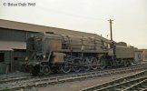
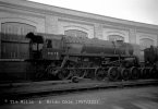
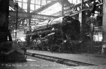
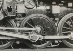
7mm Scale 7 MOK 9F in Spain

Len Cattley

Western Thunderer
It's now 2023 how time flies, have soldered the dummy hornguides, going to fit Grease Nipples but don't know if you can see the feed pipes Any ideas on this?

Len
 

Len Cattley

Western Thunderer
Also on the Brake hanger brackets, I want to make the brackets removable (there is 3 ways to achieve this) what is the best way to do this?
Len16757078777138135030052330682627.jpg
 

markjj

Western Thunderer
Also on the Brake hanger brackets, I want to make the brackets removable (there is 3 ways to achieve this) what is the best way to do this?
LenView attachment 179824
I have done the 14BA method on my 4mt tanks and tender locos it worked quite well.
I can see benefits for the 12BA method to as 12BA taps are slightly longer and more robust than 14BA ones. They are also cheaper and easier to find.
On your Grease nipple front you would need a magnified to see them I can hardly see them in a photo of a real one but if you are brave enough go for it.
 

spikey faz

Western Thunderer
Do you know were they go?
Len
Not 100% sure. There's the two that pop up over the top of the chassis and disappear into the dark recesses. The others I just routed to the various holes in the chassis. They're largely hidden, so I wasn't too fussed as this fits in with my 'impressionist' approach to my model making. I did spend quite a bit of time studying books and online references to glean more info and had I persevered I may possibly have come up with a definitive version, but I decided to call a halt.

Mike
 

spikey faz

Western Thunderer
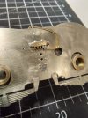
This is the only pic I took as a work in progress.

20230112_195612.jpg

The remaining three pipes (not added when pic taken) disappear into the round hole to the right. I haven't got any pics of the other oilbox. Next time I take the wheels off I'll take some pics and send them to you. But like I say I do apply some artistic licence to my interpretation! :D

Mike
 

Dave Holt

Western Thunderer
Len.
Can't give a definitive answer but, looking at some photos of un-wheeled 9F chassis in the works, suggests that at least some of the grease pipes ran along the outside of the frames to the horn guides. Beware of modelling a model rather than the real thing. There's at leat a couple of preserved examples, so perhaps someone has detailed photos or access to the information?
Might not fully answer you question, but there are some great detailed photos on here under the gallery section, last entry 29 Aug 2022 under 9F Detailed photos, or something like that.
Dave.
 
Last edited:

markjj

Western Thunderer
Len.
Can't give a definitive answer but, looking at some photos of un-wheeled 9F chassis in the works, suggests that at least some of the grease pipes ran along the outside of the frames to the horn guides. Beware of modelling a model rather than the real thing. There's at leat a couple of preserved examples, so perhaps someone has detailed photos or access to the information?
Might not fully answer you question, but there are some great detailed photos on here under the gallery section, last entry 29 Aug 2022 under 9F Detailed photos, or something like that.
Dave.
This is the link to the thread that I started before the 9f came out that you refer to above.
 

Ian@StEnochs

Western Thunderer
This is the only pic I took as a work in progress.

View attachment 179899

The remaining three pipes (not added when pic taken) disappear into the round hole to the right. I haven't got any pics of the other oilbox. Next time I take the wheels off I'll take some pics and send them to you. But like I say I do apply some artistic licence to my interpretation! :D

Mike
Mike,

The routing of the oil pipes puzzles me a wee bit. I understand that that type of oil box works by means of oil siphoning into the pipe via worsted wicks and flowing by gravity to where required. Oil could not flow up those pipes over the frames! Perhaps that round hole is where they should all go and the two over the frame are redundant but not disconnected. I assume you have a prototype photo showing them routed like that!

Ian.
 

oldravendale

Western Thunderer
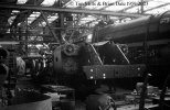
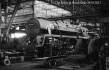
I don't know whether these will be of any help - they are hardly model makers detailed photos - but I just worked on these from Tim's collection. They'll appear later with full details, but they might be of greatest value right now and it is, after all, the type of question Tim always hoped his photos would help to answer. Both are of 9Fs being built at Swindon. Unfortunately they may not be the answer to questions about the nether regions.

92207. 25 April 1959

img3808 TM Neg Strip 14 92207 under construction Swindon works  25 Apr 59 copyright Final.jpg

92206 on the same date.

img3809 TM Neg Strip 14 92206 under construction Swindon works  25 Apr 59 copyright Final.jpg

I can do you a couple of "specials" if it will help and try to lighten up the underframe detail a bit.

And a couple of mine, my collection and copyright. 92203 at Liss as withdrawn in May 1970.

92203.  Liss.  May 1970 (5).  FINAL.jpg

92240 Southall Shed 18 July 1965

92240.  Southall Shed.  18 July 1965.  copyright FINAL.  Personal Collection.  Photo by Brian ...jpg

And I've just found a couple more of Tim's, although these have been published previously.

Newly built 92178 at Swndon 19th October 1957.

img442 TM 92178 Swindon 19 Oct 57 Newly Built 9F - Copyright Final.jpg

92185. Swindon. 19 October 1957.

img445 Swindon 19 Oct 57 Newly Built 92185 - Copyright Final.jpg

Brian
 

spikey faz

Western Thunderer
Mike,

The routing of the oil pipes puzzles me a wee bit. I understand that that type of oil box works by means of oil siphoning into the pipe via worsted wicks and flowing by gravity to where required. Oil could not flow up those pipes over the frames! Perhaps that round hole is where they should all go and the two over the frame are redundant but not disconnected. I assume you have a prototype photo showing them routed like that!

Ian.
I think you're right. :thumbs: However, I'm probably not going to change them now as I'm struggling a bit to keep motivated with the build. They're pretty much hidden away anyway.

Mike
 

OzzyO

Western Thunderer
This is the only pic I took as a work in progress.

View attachment 179899

The remaining three pipes (not added when pic taken) disappear into the round hole to the right. I haven't got any pics of the other oilbox. Next time I take the wheels off I'll take some pics and send them to you. But like I say I do apply some artistic licence to my interpretation! :D

Mike

Hello Mike,

these are not oil pipes. A oil pipe could not work like that as most oil pipes work by gravity.

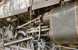
They are in fact grease pipes fed by grease nipples in about the same position. You can see it quite well in the photo below, the nipples are the round dots above the pipe work.
IMG_8473 - Copy.JPG

HTH

OzzyO.
 

spikey faz

Western Thunderer
Hello Mike,

these are not oil pipes. A oil pipe could not work like that as most oil pipes work by gravity.

They are in fact grease pipes fed by grease nipples in about the same position. You can see it quite well in the photo below, the nipples are the round dots above the pipe work.
View attachment 179965

HTH

OzzyO.
Ah! OK. That makes sense. :)

Mike
 
Top