On Michael's Workbench - Air Loco

Dog Star

Western Thunderer
Thank you Michael (@michael mott) for replying to my question about the power source. I guess that I shall have to be patient until you re-visit Bankhead for an explanation about the difference in cylinder diameters.

regards, Graham
 

simond

Western Thunderer
Graham,

Pending a definitive reply, I’ll hazard the following:

Compressed air is supplied via the regulator to the front of the valve chest of the right hand, HP cylinder, it appears to be slide valves, presumably there’s a lubricator in the air feed somewhere. After expansion in that cylinder, the exhaust from that cylinder is piped across the frames to the LH, LP, valve chest, and thence to atmosphere after expanding in that cylinder.

I suggest that the cylinder diameters are calculated so that the force provided by each at the average applied pressure is about equal. I’ve no idea what the ideal pressure ratio between HP & LP would be, though I guess it was a bread&butter question for the engineers that designed it, and I’d expect they optimised the cylinder dimensions to suit

I’d expect there to be a “simpling valve” to admit HP air to the LP cylinder for starting.

Noteworthy that the cylinders have fins, not for cooling like a motorbike, but the opposite, to get heat in from the atmosphere to provide energy for the expansion. There’s far less energy in compressed air than in a similar volume of steam at the same pressure, as there’s very limited temperature difference, and no latent heat. (Ignoring the superheated water that is probably 80% - 90% of a steam loco boiler volume )

does this help? I look forward to confirmation, clarification or correction in due course :)
Simon
.
 

Dog Star

Western Thunderer
does this help? I look forward to confirmation, clarification or correction in due course.
Thank you Simon,

What you have written is in-line with my interpretation of the photos of the front of the engine, thank you.

regards, Graham
 

J_F_S

Western Thunderer
Graham,

Pending a definitive reply, I’ll hazard the following:
...
Simon
.

I would agree with that, but would add an important rider, and it is that these locos were "self recharging" that is that they compressed the air back into the receiver whilst braking - which is also why the cylinders are finned and I suspect that the compounding was a lot more useful in the compressing phase. Since you always get less out than you put in, they must have been intended for use where there was much more braking than pulling - for example where a haulage rope did much of the up-hill effort, or where the load was brought down a hillside and only empties went back. (Ffestiniog-style)
That is quite a hefty receiver so I expect they intended it to store a fair bit of energy.

I have been trying to work out which of the levers in the "cab" switches between power and regenerative braking! And also what the valve gear look like.

You are right about how feeble air is compared to steam. In the South Wales coalfield, they converted a number of the steam winders to use compressed air to avoid renewing the boilers ... and found it to be a very expensive way of wasting power! It was always strange to enter a freezing cold engine house!

Great build - Michael:- well beyond the ordinary in every sense!!

Best Wishes,
Howard
 
Last edited:

simond

Western Thunderer
Thanks Howard, I wasn’t aware of the “regen” capability.

Adds a level of complexity, and I don’t understand how that could work with slide valves.

any more gen?

thx
Simon
 
Last edited:

simond

Western Thunderer
It's interesting that these were purpose-built. The examples I'm aware of from the UK were all conversions, such as this pair of self-recharging compressed air locos built by/for Dorman Long and, correspondingly, were less sophisticated.

South Bank Coke Ovens

Adam

Adsm,

these appear to be steam loco chassis using commercial diesel compressors as the energy source - I guess a “compressed air transmission”. Horribly inefficient, I guess but turbo-cheap if you’ve got a couple of functional chassis with duff boilers?

Atb
Simon
 

AJC

Western Thunderer
Adsm,

these appear to be steam loco chassis using commercial diesel compressors as the energy source - I guess a “compressed air transmission”. Horribly inefficient, I guess but turbo-cheap if you’ve got a couple of functional chassis with duff boilers?

Atb
Simon

That’s precisely what they were (a Peckett and a Hawthorn, Leslie). Not sure what the application they were built for: Dorman Long had a few fireless locos of a similar vintage which I imagine would be both more useful and more efficient.

Adam
 

michael mott

Western Thunderer
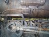
I have sent a request to my friend Martin to see if he is willing to lend his expertise on this question of the functionality of these interesting locos. As you all know it took me a while to just sort out how the brakes worked. The valve gear appears to be Stephenson.

canmore mine Railway 082.jpg

Thanks for the interesting questions and conversation around this type of Loco.

Michael
 

J_F_S

Western Thunderer
Many thanks for the excellent valve gear photo Michael. I look forward to hearing anything Martin comes up with.

I can't yet quite see how the reversing lever connects up as that might shed a bit more light on how the thing was driven - considering how basic the throttle is!

... and I don’t understand how that could work with slide valves.

I would not like anyone to see me as any kind of expert - I have only ever heard of these things in passing conversation! But, in principle, slide valves do not present any challange in this context - it is a question of setting the reversing lever in the "wrong" direction and the cylinders compress - drawing air in when the valve is open to exhaust and pushing it out when open to admission. The receiver pressure keeping the valve on its face.
I own a Fowler Ploughing engine which is not fitted with (conventional) brakes and the engine is controlled on the steep hills of Staffordshire using the reversing lever in this way - it is remarkably sensitive - and it is a slide valve compound.
More of a question to me is how the pressure limiting valve worked in reverse as some kind of bye-pass valve is needed, but since none is visible, it must be internal. Or, of course, I could be wrong - it did happen once:)
Just in passing, you remarked previously about the wire valve handles in the context of them being hot to the touch. Worth remembering that they also work when things are very cold which might be more likely here.
 

simond

Western Thunderer
slide valves do not present any challange in this context - it is a question of setting the reversing lever in the "wrong" direction and the cylinders compress - drawing air in when the valve is open to exhaust and pushing it out when open to admission. The receiver pressure keeping the valve on its face.

Howard, I beg to differ. (Though in so doing I may be mistaken, and I bow to your Fowler experience!)

Your ploughing engine will always have a higher pressure in the boiler than in the cylinders, and this will indeed keep the slide valves in place, whatever the position of the reverser, presuming the regulator is cracked open.

If our air engine is to recharge the reservoir, the pressure within the cylinders must exceed that in the reservoir, and that will tend to force the valves from the face, at which point, it just pumps air from side to side of the pistons. Moving the reverser to the opposite direction to that in which you’re travelling will certainly slow you down but I don’t think it can charge the reservoir.

There is one point here. The area of the whole slide valve (as seen from the chest) is bigger than the area of the pocket within the valve (as seen from the cylinder) and this would, in principle, allow a greater pressure within the cylinder than in the reservoir - but this ratio is surely going to be very limited. Without doing sums, (and having the dimensions of the valves) I haven’t a good idea of what difference this might make, but my guess is “not a lot”.

I'm sure that piston valves would not present any such object to refilling the reservoir by reversing the valve gear.

atb
Simon
 

J_F_S

Western Thunderer
You are of course right about the pressure differential keeping the valve seated (Porter quote the receiver pressure as 800psi and the HP as 250 - I assume everyone has seen this:- https://americanindustrialmining.com/porter-locomotives) but, when the engine is being used as a brake, the valve will be open to its admission side with the receiver pressure acting against the piston for much of the stroke, only towards the end of the stroke when the cylinder pressure exceeds the receiver will the piston begin to drive the air back into the receiver at which point the valve is still open to its admission side - ie the air compressed behind the piston is in direct communication with the "steam chest" through the open valve and so still acting to seat the valve. The valve can only be forced off its seat when the valve is closed to both its admission side and exhaust side - a situation which (other than in mid gear) only exists at the start of the stroke when the engine is running in the "wrong" direction - being the "expansion" part of the stroke in normal working.

But - to be clear - I am by no means insisting that these particular engines were used as regenerative brakes, only that I was told about similar engines which were so used. Certainly the places which Porter quotes as using them do not involve much by the way of inclines, being often tunnel construction sites - so no need of braking there!

Moreover, the extent to which energy would be recovered would be quite limited - given how high the re-charge pressure is - and that might be of limited value other than in the special kinds of applications I mentioned in my first post.

Best Wishes,
Howard
 

michael mott

Western Thunderer
Good evening all, it is 7:20pm here in Alberta and a bit chilly as well -13C
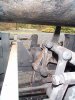
here are a few more pictures that might help answer some of your questions Howard. canmore mine Railway 056.jpg
canmore mine Railway 117.jpg
canmore mine Railway 081.jpg

The next three show the three levers at the drivers position note that the short lever inside the frames on the back of the tank only has a single notch this lever via the linkage connects to the valve at the front.
canmore mine Railway 062.jpg

In this picture the single notch is clear

canmore mine Railway 074.jpg


The inside lever on the right side of the loco is the forward reverse lever and the outside one the brake

canmore mine Railway 060.jpg

canmore mine Railway 059.jpg
I am still waiting to here from Martin so I cannot shed any further light on using the cylinders as brakes. I hope other pictures help regarding the valve operation.

Unfortunately because i have no space between the frames to model the valves on this model. they will have to wait until I can build the next one with the proper gauge and frames, I am also waiting for a drawing from Martin that he has access to from his university connections. of some of the locos that were used at Bankhead.

The Museum in Quebec has an extensive collection of Mining equipment drawings, I am hoping to get there one of these days. but it is not a quick drive being a couple thousand miles across the country. Banff is a five hour drive from my place so in the spring when the snow has gone I will be going back to Bankhead for a much better bit of measuring and photography. plus the mountains are a great place to spend a couple of days.

Michael
 

simond

Western Thunderer
Morning Michael,

my experience of Alberta is somewhat limited. My parents emigrated to Edmonton when they married in ‘54, my mum could not stand the winter cold, and my dad couldn’t manage the summer heat, so they returned to the Wirral in ‘56, thus ensuring I was born with webbed feet…

I took a three week holiday some 30 years back to travel with my mum to meet the pals she & dad had made, which involved a drive to Vancouver via Jasper & Banff.

It’s quite big, isn’t it :). (And spectacular, I’d love to go skiing there, and motorcycling, and boating…)
 

michael mott

Western Thunderer
I took a three week holiday some 30 years back to travel with my mum to meet the pals she & dad had made, which involved a drive to Vancouver via Jasper & Banff.

Simon thanks for the info, yes the drive from Edmonton to Vancouver via Jasper and Banff is one of the most spectacular drives I have ever taken. Once you get south of Lake Louise the old number 1 highway is nice and quiet away from the Trans Canada and close to Castle Junction there is a place called Johnston Canyon, we have stayed there more than any other place because there are a lot of waterfalls and I like to paint them.
however this little sketch was done at Num-Ti-Jah Lodge just south of Bow Summit pass (6,791 feet) the mountain is the crowfoot mountain at the south end of Bow Lake. size is 4" x 2"approx
christmas 2020 bow lake.jpg

And a scene from Vancouver Island. size 30"x 15" watercolour

Capture5871.JPG
I hope everyone has a great Christmas and a prosperous and healthy new year.

Michael
 

J_F_S

Western Thunderer
Good evening all, it is 7:20pm here in Alberta and a bit chilly as well -13C
here are a few more pictures that might help answer some of your questions Howard. View attachment 153619

Michael

Excellent photos Michael - many thanks and I will study with interest! I have some photos of a Porter saddle tank steamer so will make some comparisons.

Best Wishes,
Howard
 

Giles

Western Thunderer
My guess is that those slide valves may be of the 'balanced' type, and won't lift off their seats (looking at their proportions and construction from the outside...). I may be completely wrong of course!

When driving my 5"scale (10 1/4") Bagnall on our line in Pulborough which has some relatively steep gradients, I habitually used the reverser as a brake, closing the regulator, and putting her into reverse gear to act as a very effective retarder. A short breath of steam would work slow smoothly and effectively. I always had a respect for the old Casey Jones TV programme where he obviously had no engine brakes and stopped on the reverser!
 
Hi All,

Michael mentioned this site and I just signed up. His build is amazing! The history of pneumatic locomotives is a fascinating - and an ever-evolving story as new information tumbles out of the past. What follows is a quick overview of their development in north America. Originally developed in England, pneumatic locomotives arrived in north America in 1874. The first few locomotives were built by Burnham, Parry, Williams & Co. (Baldwin Locomotive Works) for drawing street cars. In 1883 they built the first pneumatic locomotive dedicated to mining service for W H Brown. Brown did much of the design work and put the locomotive to work in a Pennsylvania coal mine. The locomotive had 9x14” cylinders with a main tank that could hold 400 PSI. When Brown needed a second locomotive, he ordered it from H K Porter instead of Baldwin. I am not sure why Brown switched manufactures, but it was Porter’s first pneumatic locomotive. Construction no 1239 was built in 11/1890 and was a single stage locomotive with 8x14” cylinders.

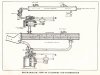
Other manufactures quickly followed suit. Early Porter, Baldwin, Vulcan and Dickson pneumatic locomotives all looked fairly similar. They typically had a high-pressure main tank (400 to 800 PSI) followed by a pressure reduction valve and an auxiliary tank around 125 to 200 PSI. From there the air went in parallel to both cylinders. You can see the auxiliary tank and parallel delivery pipes in Michael’s photos of the Bankhead locomotive. There are discussions of hauling upgrade to the mine followed by drifting downgrade to conserve air. However, I have not seen any references to regenerative braking and suspect that it was not done. There were some versions of the locomotives that applied reheaters to the auxiliary tanks to increase the efficiency. The reheaters used were either oil burners or hot water jackets. For the most part reheaters were not widely adapted – the added efficiency came with too much effort. In addition, for locomotives used inside a mine, burning oil reduced the benefit of clean air power.


This all changed in 1908 when Porter introduced a two-stage locomotive with an atmospheric interheater. Charles Hodges had come up with the idea in 1904 and assigned the patent to the Porter Co. but it took a few years to perfect the design. The initial designs had some difficulties to overcome. The temperature of air drops when it does work and this drop can be substantial. The air temperature would drop 280 deg F when it left the high pressure cylinder. At – 220 deg F, stuff froze up – lubrication was an issue, ports became clogged with ice – it was a mess. Eventually they came up with a solid design. The two-stage design is where you will see the different sizes in the cylinders. The high-pressure cylinder is fairly small in comparison the low-pressure cylinder. For example, the first, two-stage locomotive (CN4187 built in 1908) had a 5x10” high pressure cylinder and a 10x10” low pressure cylinder. The photo Michael posted of locomotive at the Canmore Museum shows the two different sized cylinders very clearly. (The photo is at the start of his thread) Although Baldwin was first north American builder of a pneumatic locomotive and a much larger company, Porter controlled critical patents and had expertise in small locomotive production. Porter went on to dominate the short-lived pneumatic locomotive market. Production peaked in 1910 with 81 locomotives but competition from electric power decimated demand. About 500 hundred compressed locomotives were produced by Porter – about 80% of market . They built their last pneumatic locomotive in 1931 for the Homestake Mining Co. Although there are some disagreements in the records, it appears that Homestake used pneumatic locomotives until 1983. German engineers refined Hodges design and introduced three-stage locomotives but they were not used in north America.

Although the large north-American manufactures were gone, in the 1950’s there was a resurgence of sorts enabled by high torque, low speed rotary air motors used to drive muckers – however that’s another story.

I am looking forward to following Michael’s progress. I will post a project of mine on another thread,

Regards

Marty Johnston

 

Osgood

Western Thunderer
800psi? Now Michael's huge 'boiler' rivets make sense!

Fascinating topic, compressed air being a logical choice for mines haulage, but I have no idea why Dorman Long would choose to use compressed air traction on coke cars (other than for maybe car emptying functions) when they had so much conventional traction available - its just a constant start/stop operation that steam, electric or fluid flywheel could do all day long.
 
Top