Building a Mike Trice designed Gauge 3 GNR open wagon

Mike W

Western Thunderer
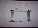
Before fixing the chassis I add the whitemetal springs. These are fairly generic castings in that I only have five types of 3ft 6in wagon springs, but these seem close enough. Note the pegs on the back of the springs and the corresponding holes in the W irons. These do two things: fix the springs and thereby the W irons at the right height - bear in mind that you can't assume that all model floors are the correct height underneath, so the crossbar may not be in contact with the floor. And the pegs also take any out of scale loads away from the more delicate ends of the springs, which will be fixed with Araldite.100_2231.JPG
 

Mike W

Western Thunderer
Mild steel can be soldered easily with ordinary soft solder and using Bakers Fluid for flux it runs just like soldering brass. Only downside of Bakers is that the steel starts to rust within seconds, so I scrub it in the sink, dry it, fix the springs and get some paint on it asap. I don't paint the tops of the crossmembers because I prefer glue to act direct onto the steel and not onto the paint which can flake off .. he says from experience!

The little pegs on the bottom of the springs locate the real coil springs.

100_2237.JPG
 

Mike W

Western Thunderer
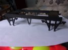
Before the chassis is fixed its convenient to fix the buffer guides. These are my own whitemetal castings and again fixed with Araldite. The only part of the body prints that I would prefer to be changed are the slots for the couplings which, being designed for 4mm are far too large in both directions. Ant at Newland 3D says he may print an adaptor plate to sit behind the beam, partially fill the hole and leave a scale sized slot. But it doesn't need to be done now and I have an idea involving some scrap brass etch, so will continue with the build and return to it later.
Mike100_2233.JPG
 
Last edited:

lankytank

Western Thunderer
Mike

Yes, that's my only 'quibble' with the print, that's a slot that you could loose a small car in - I have a work around that uses small bits of plasticard & some 4 x 2mm rectangular brass tubing, with some easing it just takes one of your 'hook shanks' & you have a metal/metal interface rather than metal/plastic.
 

Mike W

Western Thunderer
Indeed so Mike, but as a test print I'll adapt it. I thought I had some 4mm x 2mm brass rectangulat tube, but can't find it, so plan is to fabricate some from scrap etch. As a first print in a scale so much larger, if that's the only "complaint" we can find its not bad!
Mike
 

Lawrence Boul

Western Thunderer
Alternative option is the modify the supplied .stls or import the .obj file into your favourite modelling software. Probably less faff.
I've made similar comments to numerous parties many times. Perhaps unsurprisingly, given established practise, some modellers look at 3D prints as a starting point to kit bash/modify. This is entirely possible, but often not particularly sensible. Carving details off or filling a print is far more difficult and generally far less effective than doing it digitally and reprinting. That assumes the owner of the file/printer is prepared to do that, but it's always worth asking.
 

Mike W

Western Thunderer
You are quite right. However, Gauge 3 is a minority scale, so it may be unreasonable to ask a manufacturer to change very much just for a handful of models. For that reason I'm happy to accept even a scratch-building aid. This model however is far more than that - its a full kit and the coupling hook slot is so minor that I almost wish I hadn't mentioned it. Scottish Wagon Works was another company who bent over backwards to help with a G3 version. As you say Lawrence - its always worth asking.
Mike
 

John_B

Western Thunderer
Carving details off or filling a print is far more difficult and generally far less effective than doing it digitally and reprinting. That assumes the owner of the file/printer is prepared to do that, but it's always worth asking.
I've found it's often not particularly easy to modify files. I've been struggling to get my head round it. A lot of downloaded files have errors in them that don't help, and I've found it difficult to find clear instructions on the best way to do it. I've currently got one that I haven't been able to edit in FreeCAD, as my computer grinds to a halt when I try. I'll try Blender some time, but haven't used it for ages, so need to learn it again, although I often haven't had great success with that either. Sometimes it would be easier just to do some physical kit-bashing!

I suppose sellers of 3D prints would have more skill than me, but I've only bought one 3D printed model, and that has detail so fine that some of it needs to be replaced by metal parts, as it's too delicate to be used as a working model!
 

Lawrence Boul

Western Thunderer
You are quite right. However, Gauge 3 is a minority scale, so it may be unreasonable to ask a manufacturer to change very much just for a handful of models. For that reason I'm happy to accept even a scratch-building aid. This model however is far more than that - its a full kit and the coupling hook slot is so minor that I almost wish I hadn't mentioned it. Scottish Wagon Works was another company who bent over backwards to help with a G3 version. As you say Lawrence - its always worth asking.
Mike
The larger the scale, the more cost is involved with reprinting - so yes, filling that slot is probably the answer. One of the things with digital modelling though is that things do not always translate effort wise from the real world. Reducing a slot size is almost trivial, and depending on workflow making the change and repreparing the print might be less than a minute. Other things you might think would be easy can sometimes be a lot more time-consuming. But there are still costs associated with printing and reprinting so that needs to be considered.
 

Lawrence Boul

Western Thunderer
I've found it's often not particularly easy to modify files. I've been struggling to get my head round it. A lot of downloaded files have errors in them that don't help, and I've found it difficult to find clear instructions on the best way to do it. I've currently got one that I haven't been able to edit in FreeCAD, as my computer grinds to a halt when I try. I'll try Blender some time, but haven't used it for ages, so need to learn it again, although I often haven't had great success with that either. Sometimes it would be easier just to do some physical kit-bashing!

I suppose sellers of 3D prints would have more skill than me, but I've only bought one 3D printed model, and that has detail so fine that some of it needs to be replaced by metal parts, as it's too delicate to be used as a working model!
This is actually a totally different issue John. A model in editable CAD (such as produced by a kit designer) will typically consist of separate parts much like the real thing and, depending on the discipline shown in construction, will normally be very easy to alter in the original model (provided redrawing of parts isn't required) . A downloaded stl is totally different, and is typically harder to manipulate. It's not impossible, but it's a different skillset and generally not nearly as slick.
 

Mike Trice

Western Thunderer
This is actually a totally different issue John. A model in editable CAD (such as produced by a kit designer) will typically consist of separate parts much like the real thing and, depending on the discipline shown in construction, will normally be very easy to alter in the original model (provided redrawing of parts isn't required) . A downloaded stl is totally different, and is typically harder to manipulate. It's not impossible, but it's a different skillset and generally not nearly as slick.
Which is why I now include the .obj file as well so the .stls can be bypassed.
 

Lawrence Boul

Western Thunderer
Which is why I now include the .obj file as well so the .stls can be bypassed.
Very laudable. I think you are unusual in making such models freely available though. In many cases providing stls that are hard to edit is a commercial advantage. In my own case you don't get any file - just prints. So if you want to modify them it's a case of carve or ask nicely.
 

Mike W

Western Thunderer
Having written that "Gauge 3 is a minority scale", just for interest, over the last 20 years I've sold over 100 sets of those GNR buffers, some with my own van kits and many for non-GNR subjects for which the customers consider them to be a close match.
Mike
 

Ian_T

Western Thunderer
For what it's worth, I spent time trying to repair and modify STL files some time ago. I use Soild Edge these days and it has some very sophisticated tools available in this area - assuming of course you understand what you are doing, which I certainly didn't.

STL files basically don't have enough information in them to make them 'editable' as such when imported back in a native CAD format. Some problems can be addressed (for instance mesh "repairs") but you can't just 'load & edit' them back into CAD. The surfaces are not sufficiently well defined for instance to make a 'join' with another (new) part.

I did find some simple work-arounds however. I could slice or cut parts off the STL model fairly easily for instance, which then gave me a sufficiently well defined surface. An example of this was a 'wheel' STL that had a coarse wheel profile. I cut the entire flange & tread off the original STL model and designed a new flange/tread (in SE) that met G3S wheel standards. I was then able to assemble the two parts together and produce a new part - from which a STL file could be exported & printed. Not a solution for all issues but it can be very helpful sometimes. For instance, got a flat surface that won't 'mate'? Take a very (0.02mm) thin slice off that surface and it will then mate with the other part...

The image below shows the modified wheel part and the new 'flange' parts before assembly.

Regards,

IanT

Modified_Wheel_Parts.jpg
 

Lawrence Boul

Western Thunderer
For what it's worth, I spent time trying to repair and modify STL files some time ago. I use Soild Edge these days and it has some very sophisticated tools available in this area - assuming of course you understand what you are doing, which I certainly didn't.

STL files basically don't have enough information in them to make them 'editable' as such when imported back in a native CAD format. Some problems can be addressed (for instance mesh "repairs") but you can't just 'load & edit' them back into CAD. The surfaces are not sufficiently well defined for instance to make a 'join' with another (new) part.

I did find some simple work-arounds however. I could slice or cut parts off the STL model fairly easily for instance, which then gave me a sufficiently well defined surface. An example of this was a 'wheel' STL that had a coarse wheel profile. I cut the entire flange & tread off the original STL model and designed a new flange/tread (in SE) that met G3S wheel standards. I was then able to assemble the two parts together and produce a new part - from which a STL file could be exported & printed. Not a solution for all issues but it can be very helpful sometimes. For instance, got a flat surface that won't 'mate'? Take a very (0.02mm) thin slice off that surface and it will then mate with the other part...

The image below shows the modified wheel part and the new 'flange' parts before assembly.

Regards,

IanT

View attachment 269498

Things move on and software differs. It's certainly true that stl files do not contain the same information in the same way that CAD does. Rhino has 'shrink wrap' and 'quad remesh' features that are very useful for dealing with things like scan data and stls. Software like Blender has tools to 'retopologise', which is another way of saying turning a bunch of messy triangles into something more structured in quads. Other software will too. AI features are starting to creep in and these may make this easier in future.

But these tools are not all that helpful for the 'hard surface' modelling that we typically do. Much more so for organic and soft surfaces.
If you like playing around with software, then this all enriches a hobby that's already diverse. If you don't then it's a hassle that you can live without. Like any other skill there's a learning curve and experience is valuable.

As a general principle I feel reverse engineering stls is a poor idea:
  • First up you are pinching somebody's work. If they are happy for you to have it they will offer a better format (as Mike has). Always worth asking.
  • stls are comprised of triangles and thus all curves are approximations and there is no symmetry. The quality of the file is outside your control. Good for printing, not so good as a basis for editing.
  • It's generally not that easy. Generating that wheel centre in CAD should be very easy and quick. If you don't have those skills it would probably be more useful to learn them than trying to cobble together stls.
  • It's the old 'model of a model' trap. You are starting with somebody else's model to make your own rather than starting from prototype data.
On the other hand Boolean operations generally work well, so adding or removing features (narrowing coupler slots) should be relatively simple. The stl may also be a candidate for distressing a model (adding dents etc), although a quad model is better. Adding cracks to boards, distortion, dropped hinges etc improve realism a lot. Cracks should be easy to do on the stl, the other work would probably need a quad model , ideally with separate parts.

In this 1:64 wagon the model was started in AutoCAD and finished in Rhino (for reasons of software availability and cost). It was then transferred to Blender to add wood grain, drop the doors, distress boards, add chains etc. This condition is similar to the prototype image earlier in the thread. I haven't looked at Mike's files, but quite possibly a similar approach could be taken. Not on the stls though!

L-4732.jpg
 

Ian_T

Western Thunderer
I agree to some extent with your comments Lawrence, however sometimes it's much easier to make a small change than start over.

In the case of the wheel, this was part of a set of STLs for a G3 engine that had been upscaled by it's author from his G1 model. I was in correspondence with him about making the files available to the G3 community and printed a 'test' version of the G3 model to evaluate it. The original wheel flanges were hitting the tops of my track chairs, so I modified them to G3S standards and sent the revised STL to him for his approval. He suggested a small alignment change, which I made and he then incorporated the revised wheel STL into his set. It was a detail I cared about but which didn't particularly bother him (either way) - so I did the work.

This was a simple example but there are often times when it is much simpler to modify an existing design than to recreate it. This would be very true of models involving swept surfaces for instance. If you have a complex impeller design with the wrong sized bore (& keyway) then it is much easier to modify it this way than re-draw it (assuming that was possible without the having original design data).

Regards,

IanT
 

NickB

Western Thunderer
Having written that "Gauge 3 is a minority scale", just for interest, over the last 20 years I've sold over 100 sets of those GNR buffers

Two thoughts occur (not mutually exclusive!).

1. Perhaps there are a lot more people modelling in G3 than join or are active in the G3 Society, attend exhibitions, or post online. Quite likely. For some, modelling is a private matter, possibly shared with a few friends (and/or the grandchildren) but not more than that.

2. Hoarding. Some people in all scales appear to have cupboards full of unbuilt kits and bits. Either they buy, intending to build it but somehow never quite starting it, or they are mindful that most production runs are short and they want to be sure to have stocks before it sells out.

It would be nice to know numbers or percentages, but by the nature of the problem, very difficult to find out.

Nick
 

lankytank

Western Thunderer
Nick

Think you've hit it fairly square with your Point 2.

Lost count of the number of times I've not bought something, only to find myself searching out that self same thing 8 or 10 (or more) years down the line & having to pay a premium to get it.

Got a mate, who, whilst we were putting to the world to rights, one day, - philosophically came out with the statement 'I'd rather be looking at it, than looking for it!'

Seems to be a life mantra :thumbs:
 

T30rra

Western Thunderer
I will put my 10 pence in... the likes of blender is far from intuitive and you need to invest a great deal of hours in learning how to use it properly which I dont have. I tend to use Fusion 360 but that in itself is also limited in what it can do or at least what is simple to do within it.

Take coach seating for example, with the buttoned cushions, from previous exploration it is extremely difficult to produce those complex shapes in Fusion.

Anyhow, I did upload the GNR wagon .obj file into 3D viewer to ungroup the files and edit them, thats how I managed to seperate the buffers, omit the chain detail etc. but I have to admit it did not occur to me to open it with Fusion to see if the coupling slot can simply be narrowed in there. As Mike T says, if so, it is considerably less faff.
 
Top