For what it's worth, I spent time trying to repair and modify STL files some time ago. I use Soild Edge these days and it has some very sophisticated tools available in this area - assuming of course you understand what you are doing, which I certainly didn't.
STL files basically don't have enough information in them to make them 'editable' as such when imported back in a native CAD format. Some problems can be addressed (for instance mesh "repairs") but you can't just 'load & edit' them back into CAD. The surfaces are not sufficiently well defined for instance to make a 'join' with another (new) part.
I did find some simple work-arounds however. I could slice or cut parts off the STL model fairly easily for instance, which then gave me a sufficiently well defined surface. An example of this was a 'wheel' STL that had a coarse wheel profile. I cut the entire flange & tread off the original STL model and designed a new flange/tread (in SE) that met G3S wheel standards. I was then able to assemble the two parts together and produce a new part - from which a STL file could be exported & printed. Not a solution for all issues but it can be very helpful sometimes. For instance, got a flat surface that won't 'mate'? Take a very (0.02mm) thin slice off that surface and it will then mate with the other part...
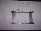
The image below shows the modified wheel part and the new 'flange' parts before assembly.
Regards,
IanT
View attachment 269498