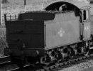
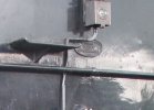
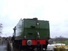
B1 - 61161

65179

Active Member
Mmmm. Four, I think, Simon.
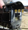
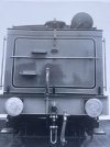
The preserved 1264, that I based my speedo mounting design on, uses 4 slot headed countersunk screws that are flush with the outside face of the valence. I thought wouldn't really show on a 4 mm scale model, so didn't bother. However, checking photos of loco in service, in the Yeadon book, seem to show snap head fixings, which definitely do show. Have you any decent , side-on, photos or drawing showing the attachment arrangements?
Just goes to show the dangers of using preserved locos for information.
Dave.

I was going off this image I posted before:

Post in thread 'B1 - 61161' B1 - 61161

but now you mention it the last rivet is probably in shadow.

Simon
 

Dave Holt

Western Thunderer
Thanks for the additional photos, Simon.

Fully appreciated as a joke, but it has made me think that the original snap head fixings are quite noticeable. So, I've designed a simple drilling jig that locates on the speedometer mount and up against the protruding footplate edge. Whether or not I use it is for a later decision as the holes would be rather close to the edge of the footplate plastic moulding, with the risk of breaking out. We'll see.
I'm trying to get down to progressing the tender and have added some lead ballast to the chassis, fixed using slow setting Araldite - don't want any risk of it coming loose in future.

Dave.
 

65179

Active Member
Thanks for the additional photos, Simon.

Fully appreciated as a joke, but it has made me think that the original snap head fixings are quite noticeable. So, I've designed a simple drilling jig that locates on the speedometer mount and up against the protruding footplate edge. Whether or not I use it is for a later decision as the holes would be rather close to the edge of the footplate plastic moulding, with the risk of breaking out. We'll see.
I'm trying to get down to progressing the tender and have added some lead ballast to the chassis, fixed using slow setting Araldite - don't want any risk of it coming loose in future.

Dave.

Possibly a job for rivet decals (Archer or similar)?
 

Dave Holt

Western Thunderer
I bought a sheet of Archers rivets years ago, for possible use on the C13 tank patches (but ended up with half etched N/S overlays), but have never used them. I have no idea where they are now.
Anyway, attention has turned back to the tender.
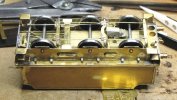
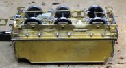
I had intended to paint the inner parts if the chassis before fitting the wheels but have got a bit carried away and the wheels and bottom cross members (which in effect make the wheel sets captive) have been fitted after attaching the spring wires to the bearing carriers. You can just make out that parts of the chassis have been painted with etch primer, as seen below.
Here's the current state of the chassis, with the scoop operating rod temporarily fitted using 0.35 mm drill bits through the forked ends.
B1_133.JPG
In the instructions, it mentions that the scoop rod passes through some sort of guide. where it passes under the front cross stretcher. Has anyone any information about the nature and position of this guide?
Dave.
 
Top