On Michael's workbench- Penrhyn Loco No. 5

michael mott

Western Thunderer
I have wanted to build a model of this locomotive for some time now. Simon Harris of Model Earth has done a kit that is representative in 7/8th scale. But it hides the wheels, and I rather like the curly spoke wheels that are on the real loco. The other reason for wanting to build this model is because when I was growing up on Twyford Avenue in west London, across the street a wonderful couple Mr and Mrs Richardson would take a "motorcar ride" every Sunday morning rain or shine in their Bullnose Morris Cowley like this one it had a cone drive and was immaculate. Their house still had gas lighting, and as kids we would often go and ask them if they had a shilling for 2 sixpences for our electric meter, they always had one.
There were a number of petrol locomotives at the Penrhyn Quarry and No 5 was still running in 1960.

I have done a drawing which I cobbled together from the couple of photographs in the special publication on the Penrhyn Quarry done by the 16mm association. I also wanted to build it to 7/8th scale.
Bob Gamble did a nice model in 16mm
So the first order of business is to make some curly spoke wheels, that fit my drawing. I decided to use brass because I have some and it is easy to work with. I started with the rims and hubs and turned up some rounded rings for making the spokes.

Capture3724.JPG

I opted for 6 spokes because it was easy to divide the spin indexer by 6 and impossible to use it to make 7. I cut grooves into the hubs and also a shallow scallop into the backside of the rims as locators for the curved spokes.

IMG_3725x1024.jpg

By trial and error I made the first couple of spokes to test the concept. The next thing to do was make some jigs for setting up the finessing of the spokes and to ensure that they were all basically the same. Doing this stuff manually can be tedious but I only have manual machines and hand tools.

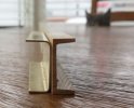
I worked out four operations for the shaping of the spokes and made some maple positioning jigs to set the spokes in my little vice that I made as an apprentice toolmaker 50 odd years ago.

Capture3729.JPG

#1 ensures that the spoke is the correct length.

#2 is for setting the angle and projecting amount to file the relief on the front edge.

#3 is for setting the correct angle and projection for filing the curved end to match the rim.

#4 is to set the angle and projection to file the slight bevel at the hub end.

An Applewood holding jig was turned up and left in the three jaw chuck to ensure everything was concentric after soldering up the assembly. The hub was glued with ACC glue to a 1/4 inch shaft for the duration of the assembly process.

Capture3726.JPG

I did not take any pictures of the step before soldering. I used soft solder and the hot air gun to heat up the assembly. it does look ugly I couldn't find my invisible solder.

Capture3733.JPG

However it cleaned op well and I used enough solder to create the filleting at the rim.

and placed over the drawing.

IMG_3736x1024.jpg

Another journey begun.

Michael
 

PhilH

Western Thunderer
I found a petrol loco frame at Penrhyn in January 1965 but there was no means of identifying which loco it was from. However I think the heavy channel frame sprung versions (Nos. 3 to 7) may have been fairly similar in dimensions.


3924B Penrhyn petrol loco chassis © PGH.jpg

Dimensions I took at the time were:
Frame side channels - 9" x 3½"
Wheel dia. - 1'- 3"
Wheelbase - 3'- 0"
Length over frames - 9'- 0" (side channels)
Length over buffer beams - 9'- 1"
Overhangs front & rear - 3'- 0" (3'- 0½" including buffer beams)
Width over frames - 3'- 1"
Height top frames to rail level - 1'- 9"

I have two photos of No.5 working, one dated 1942 the other undated but possibly taken at the same time. It was still fitted with the sloping cab roof. According to Industrial Railway Society records No.5 was stripped to the frame only by 1949, but No.3 was still in use until 1964 at least.
If the photos are any use I could copy and send with a PM as for copyright reasons I can't really post them here.
 
Last edited:

michael mott

Western Thunderer
Armed with the new information I revisited my guesstimate drawing and input the new data. My wheels were correct within .020" diameter I can live with that.
IMG_3746x1024.jpg
IMG_3747x1024.jpg

I feel better now about the proportions which I had originally pulled off an oblique image in the 16 mm associations Penrhyn special publication.
I am looking forward to panel-beating the radiator shell, I have small piece of silver that I can use.

Michael
 

PhilH

Western Thunderer
Michael,
Photos sent, they are fairly large file sizes so I hope they come through OK.
You may be aware of this but Slaters do a 7/8" scale curly 7 spoke 15" dia wheel as used on Penrhyn wagons and the petrol locos, obviously no comparison to your lovely wheels but might be useful if you're considering building any wagons to go with the loco.
Philip
 

michael mott

Western Thunderer
Hi Philip, Thanks for the photographs they are great, I shall look into the Slaters wheels for potential wagons.

Michael
 

michael mott

Western Thunderer
Thought I would have a go at shaping the radiator cowl
first to turn a form out of maple. it is 1.09" diameter

IMG_3750x1024.jpg

I started by wrapping a rectangle of the silver around and used my leather headed mallet to begin shaping and quickly realized My fingers were not strong enough to clamp the metal as I tapped so after also snipping off the top corners used a hose clamp to hold the metal around the form.

IMG_3751x1024.jpg
I did not count how many times I annealed the silver but it was more than 5

IMG_3757x1024.jpg

I am quite chuffed at the way it turned out.

IMG_3752x1024.jpg

Then a bit of work with some 400 grit wet and dry, then a bit of label paper to sort out where the hole will get cut for the front opening The shape is just a guess at the moment I need to find a drawing of the Morris Cowley.

IMG_3763x1024.jpg

IMG_3765x1024.jpg

Time for tea.

Michael
 

Giles

Western Thunderer
I'm very impressed that you can work that thickness into a hemisphere that small, that well And cleanly ! Lovely.
 

michael mott

Western Thunderer
Thanks for all the likes, and Thank you Giles for your kind words, There is a funny story around that particular piece of silver. Many years ago at least 20 I spent some time attending the Wednesday morning classes of my silver-smithing friend Karen Cantine and she thought that because of my metalworking skills that I would take to raising metal like a duck to water..... well after a few classes I had managed to turn this 4 inch disd of silver into a really crude looking dishlike cuplike mess , but being like a dog with a bone I continued onward until I broke through the bottom essentially turning that disk into an ugly tube. Humility in the presence of a master was the order of the day. I decided that raising was not my cut of tea, and went on to do a few other nice little fabricated pieces. I sut the tube open and flattened out the rectangle of silver with tapered thickness from the one long edged to the opposite and put it way until yesterday. during those intervening years I have shaped a few bits of copper and brass for various models including thes half cowl vents for a 1/8th scale Bristol Pilot Cutter

Capture0424.JPG

dressmakers pins machined to look like round headed screws.

IMG_0429x1024.jpg


IMG_0432x1024.jpg


The cutter which is an ongoing project all the rigging and blocks are made by me using thread and boxwood and is fully functional but the cutter is another story.

IMG_0374x1024.jpg

So I was fairly confident that I could pull it off. The hose clamp was out of desperation, (Karen would be horrified)

Ian thank you so much for the modelmaker plans, and as a coincidence the cutter model was derived from the modelmaker plans for the fishing smack Kingfisher. What a small world!.

Michael
 

michael mott

Western Thunderer
Some obvious tweaking needed but I guessed fairly close.
Capture3767.JPG

Capture3769.JPG

I definitely need to straighted the wonky bottom edge. photographs can be brutally honest.
I think that on the Penrhyn loco they used a new top part of the hood because there is a definite difference in the shape . further searching for images of the bull-nose Cowley donor cars reveals qhite a few subtle variations in the shapes of the hood (bonnet) and radiator depending on the year and model. so being that the model is a model I think I can live with a few minor tweaks.

Michael
 

michael mott

Western Thunderer
Table saw, Jeweler saw, and bending break work today. Folded up some channels I'll see how they look when assembled, I have been contemplating machining them out of solid in order to get the correct profile.

IMG_3771x1024.jpg


IMG_3772x1024.jpg

Machining them would also mean making a cutter to machine the angle and radius on the walls. Could be done with a bit of hard aluminium alloy. I might have some 1/4 plate... hmmmm something to think about tomorrow.

Michael
 

michael mott

Western Thunderer
Proof of concept with a bit of yellow cedar.

Capture3773.JPG

and a correct dimension section using Castello Boxwood, which is a modern substitute for English Boxwood, extremely fine grain and very stable and strong. I think I will make the frame sections this way.

Michael
 

Attachments

  • Capture3779.JPG
    Capture3779.JPG
    31.4 KB · Views: 5

michael mott

Western Thunderer
The wood worked out well enough.
Capture3791.JPG

Capture3792.JPG

I will use the brass corner plates and the Angles on the inside. The row of holes along the underside of the top flange of the channel was to hold the Morris chassis, so I am guessing that they basically used the car chassis and simply beefed it up a lot! I might thin down the flanges a tad yet.


Michael
 

michael mott

Western Thunderer
As a follow up to the assembling of the frames.
I have been using 1/8th brass rod in the C5 collet chuck, One of the issues with collet chucks is the fact that they recede into the chuck as the collet is tightened, This means that one has to compensate for the change in distance when setting up stops for repeatable operations such as screws and other small parts. I have dispensed with a fixed way to set the distance from the face of the collet, and use some parallel jaw pliers with a datum mark for small objects that are withing a 2-5 thou tolerance for length.
1 grip the rod.
IMG_3799x1024.jpg

2 push the rod into the collet and the end of the pliers bumps into the collet then release the pliers.

IMG_3800x1024.jpg

3 Next set the double ended locking stop for the first operation this is done using the left hand stop lock collar. this ensures the cutter moves to the correct length.

IMG_3801x1024.jpg

4 I have found that for many shall parts that the small .050" wide short length parting tool is great for a multitude of operations and is ground to create a sharp square bottom cut. The screw diameter is cut in one pass bringing the 1/8th rod down to .060".

IMG_3802x1024.jpg

5 Next the double ended stop is set for the second cut in this case to reduce the 1/8th to the diameter required for filing the hex.head This is done with the right hand stop collar, and you can see that left hand collar has moved away from the main block by the additional amount of travel for the tool bit.

IMG_3803x1024.jpg
6 The cut is made and the tool bit retracted to allow the 0x 80 die to be moved into position for the threading.

IMG_3804x1024.jpg
7 The die is held in a simple sliding holder that is located in the tailstock, it is made from some mild steel and there are two different heads for different diameter dies. The threading is done by rotating the chuck using the large drive belt wheel. I have made a simple handle from a file handle with an Ikea type furniture bolt protruding out so that I can easily rotate the wheel.

IMG_3806x1024.jpg

8 Cranking the wheel with the handle as the die is engaged with the brass rod. then winding it back out. This method is so much easier than pulling the wheel round by gripping it .

IMG_3807x1024.jpg

9 the die is retracted ready for setting up the parting off.
IMG_3805x1024.jpg

IMG_3808x1024.jpg

10 using the same tool bit now to part off all it needs is to be wound into the work as the distance was set before when reducing the diameter for the head, the tool was moved an extra .080' leaving .030 for the with of the head.

IMG_3811x1024.jpg
11 the small spigot left on the head end of the screw as it parts off (basically shears off one it get to be .020") is snipped off with some flush cut pliers. before being transferred to a hex pin chuck. The hex of the pin chuck acts as a visual guide for the filing. (A note here that I subscribe to the Karate Kid method of "wax on, wax off" method off body memory for this sort of filing. I have had a lot of practice. each face is 8 strokes only for this particular screw.)

IMG_3813x1024.jpg

12 After the 64 strokes it becomes a rhythm unto itself, the pin chuck is removed from the vice and the head inspected.

IMG_3817x1024.jpg
13 A 400 grit sanding stick is used to polish the top of the head ( more Wax on wax off body memory stuff but a different motion)then removed from the chuck. And I use the same principles for a number of different types of screws.

Capture3820.JPG

Most of the frame is now bolted together.

IMG_3826x1024.jpg

I hope that some of this is useful to those who are interested.

Michael
 
Top