
You are using an out of date browser. It may not display this or other websites correctly.
You should upgrade or use an alternative browser.
You should upgrade or use an alternative browser.
On Michael's workbench- Penrhyn Loco No. 5
- Thread starter michael mott
- Start date


michael mott
Western Thunderer
Now that the motor fits inside the rea body section, I have been drawing as best an interpretation from all the photographs on the net of bull nose morris cars with the bonnet open showing off their engines. I also realize that there were different engines in the various models. Here is my interpretation of an engine so far relative to the radiator of the original car.
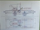

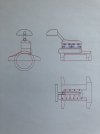
I won't be able to fit the entire engine in place because of the switches but at least most of what can be seen when the bonnet is opened will be there. It will be pretty small anyway.
Michael
I won't be able to fit the entire engine in place because of the switches but at least most of what can be seen when the bonnet is opened will be there. It will be pretty small anyway.
Michael
michael mott
Western Thunderer
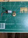
After reading through Nick Dunhill's latest Thread. I decided I could do much better. Another case of one step forward and two or three back for me this time. I have abandoned the original location and drive train also the clunky switches so that I can put the whole morris engine under the bonnet. a new worm and gear will now fit directly to the drive wheel axle.


Time for bed
Michael
Time for bed
Michael
michael mott
Western Thunderer
A couple more corrections to be made one a bit more of a pain than the other. I need to change the size of the radiator shell opening and increase the radius of the curve at the top of the rear part of the body.

The radiator will have a bath in a jar of Acetone which will unglue the core. and the rear body will need unsoldering and some new rivets holding the roof supports and the angles at the bottom moved up.....rabbit holes don't you just love them!
Michael
The radiator will have a bath in a jar of Acetone which will unglue the core. and the rear body will need unsoldering and some new rivets holding the roof supports and the angles at the bottom moved up.....rabbit holes don't you just love them!
Michael
michael mott
Western Thunderer
step one
Michael
Michael
michael mott
Western Thunderer
step two opened up the radiator shell using a few sheets of thin ply and some styrene to get .103" after removing the bulk with the jewellers saw thesheets ensured that the filing was level
next a simple wooden peg jig to reglue pairs together


polishing the front edge the gluing them back in a very tedious job for sure.
now time for supper.
Michael
next a simple wooden peg jig to reglue pairs together
polishing the front edge the gluing them back in a very tedious job for sure.
now time for supper.
Michael

michael mott
Western Thunderer
I have continued to work on trying to get the grill looking right and have gone through a couple more iterations of plate assembly only to end up dropping the lot back into the jar of acetone.

My current plan is to build an external assembly jig, and to use it to place the plates one at a time without using bits of rod to line up the plates, but to use one end as a register. I have set up a new press to make sure the plates are consistent.
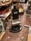
first a match set of curved forms were turned up on the myford the bottom one will function as the register.

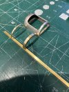
The top one will be where the gluing will happen. The brass forms will be coated on the areas that the plates will touch with reg carpenters PVA glue to prevent the CA glue from bonding the plates to the brass. Once all the plates are glued the a soak in isopropyl alcohol will dissolve the PVA for me to add some epoxy on the bottom edge of the plate block. The jig will be set up at an angle so that as each new plate is added it will fall into position and a visual check to ensure the proper alignment and trim if needed before gluing.
Well thats the plan......
Michael
My current plan is to build an external assembly jig, and to use it to place the plates one at a time without using bits of rod to line up the plates, but to use one end as a register. I have set up a new press to make sure the plates are consistent.
first a match set of curved forms were turned up on the myford the bottom one will function as the register.
The top one will be where the gluing will happen. The brass forms will be coated on the areas that the plates will touch with reg carpenters PVA glue to prevent the CA glue from bonding the plates to the brass. Once all the plates are glued the a soak in isopropyl alcohol will dissolve the PVA for me to add some epoxy on the bottom edge of the plate block. The jig will be set up at an angle so that as each new plate is added it will fall into position and a visual check to ensure the proper alignment and trim if needed before gluing.
Well thats the plan......
Michael