Richard Gawler
Western Thunderer
I have ended up with barely +/- half a millimetre of movement on my MW class F (0-4-0) and it occurs to me, this will be fine for undulations in the rails and my own 0-MF points, but not the wheel drop at some crossings on friend's layouts.The very tight clearances behind the crossheads mean I do not want the front axle to rock much, it'll need to move a bit, but only a bit...
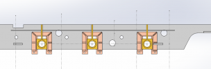
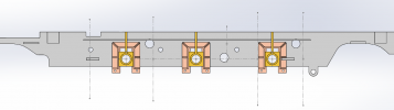
For an 0-6-0, would it be possible to make the rear axle rigid, put a rocking axle at the front, and some gentle springs to hold the middle wheels onto the rails? The springs being sufficiently gentle to hold the wheels down but not to take the weight of the loco and lift one end off the track.
")