SimonD’s workbench

Pencarrow

Western Thunderer
Well, I've done no actual modelling today. But lots of digital modelling, which has raised a few issues, I think 1366 panniers are supposed to be challenging.

View attachment 200224

we have an assembly of frames, wheels, cylinders, motor and footplate.

View attachment 200225

the main issues are to do with stuff being in the way of the CSB.

Frame spacers - assuming I use the Premier frames that Chris purchased, I either make some new spacers, or get Billy to do so (he's going to offer wider spacers - 25.6mm , at some point). Chances are I will need to make them because the body fixing holes do not align with the chassis. In any case, they will need to accept the CSB wires both front and rear.

Frames. Surprisingly the Premier frames are shorter than they should be, by several mm. Not an issue. I can make a new rear frame spacer to pick up the body mounting screw, but of course, it'll be in the way of the rear coupling spring, because the screw goes into a captive nut in the bunker.

The motion bracket is nothing at all like the drawings of the loco that Chris gave me. I have redesiged it and will make a new one. Probably a fretsaw job. This will provide a fulcrum point between the leading and driving axles. Similarly there will need to be a visual frame spacer between the cylinders, that's an easy win.

Pick-ups. I have put in my own design. The leading and driving axles are fine. The rear axle pickups interfere with the CSB. There is nowhere else to put the pickups if they are an across-the-frames design as the gearbox is in the way. Small wheels... Might need to put back-scratchers on the rear axle :(

Weight - it's heavy, but the distribution is not ideal. Accordingly I have a 136g bag of lead shot which pretty much fills the bunker. That gets the all up weight to around 850g, and the CoG back to somewhere in the middle. That, in turn, allows the weight distribution on the axles to be about 35% on the front and rear, and 30% on the middle, which will hopefully avoid the thing porpoising.

At this point, I am wondering if it might be worthwhile programming the big mill at work and simply making new frames, but the jury's out on that at the moment. I have a CRT/POWsides 1361 saddle tank to build for myself, and some 1.2mm engraving brass, so maybe two birds with one stone... (or three, if I decide to upgrade my own 1366!)

View attachment 200226

Can't think of a better way to spend a wet Saturday, but I'd have liked to have solved more problems than I've found!

Great to see it in 3d CAD! Interesting that the blessed beastie is causing you to scratch you head a little bit too, makes me feel marginally better that I waved the white flag.

Yes I noticed that the frames were short. I did look into this a while back and wondered if the were packing pieces at the rear behind the buffer beam. Very difficult to find clear photos of the rear of these locos - the few of the rear and those that there are often have the rear underneath in shadow.

Regarding the weight... I did intend to add more in the rear bunker but as you have found... I didn't get that far. The idea was to sort the chassis first and I wasn't sure if I was going to need to move the rear fixing points. That's my excuse anyway.
 

Pencarrow

Western Thunderer
Just to bring the 45xx saga to a conclusion, CSB works.

There’s no Keep Alive cap in here, the plasticard is 0.81mm thick, and the loco is weighted too far aft so the rear axle is by far the stiffest spring rate (ie the fulcrums are close to the axle) and so it reacts visible on that axle but the pickup works very well on the axles that are not on the plastic!

The 1366 is going to be fiddly - I’m not sure how keen I could get for split axles, though that works too.

Is the ultimate CSB & Split axle pickup? (Plus sound, ultrasonic smoke and synchronised firebox glow, obviously… :) )

Anyway


Bet you're pleased with that!
 

simond

Western Thunderer
thanks Adrian.

As I said, I think it performs better than “one fixed axle” compensation and is as easy as, or easier than, “all axles compensated” to build. These approaches have been my normal practice since I built my Finney 47xx which was the second 7mm loco I built.

I quite like having “go-to” solutions, on which I can rely. The pickups derived from DLOS‘ design, for example. I’ve now got a convenient & reliable way of machining and modifying Slaters axleboxes & hornguides, the drilled brass angle is easy to reproduce, and the Excel calcs on the CLAG website are useable, so the building blocks are all in place. I found the split axles process a bit tedious, I guess I’m lazy, I’d buy them ready made, but actually they’re not difficult either.

I’ve done a load of CAD work for Chris’ 1366, and run into a couple of snags, so that’s not yet quite got to the point where I’m ready to pull the trigger, but that will be CSB for sure. Once I’ve got that to work, I guess I’ll see if there’s a better way of doing it, but I think the remaining kits I have (a mogul, a large prairie and a 1361 ST) will probably get CSB too. I also recently purchased a JLTRT Saint, I’ll have to see with that one, and I have a Manor which I’m re-engineering for a pal, I suspect that will be too.

Looking back up the thread, there were a couple of comments re weight, particularly if the loco has not yet been built. I guess for a loco without bogies, I’d aim to get the COG in the middle of the coupled wheelbase, and then adjust ballast and wire size to get the height right. The static deflections I’ve calculated so far are of the order of a millimetre, so it’s not going to be ridiculous if it’s a tiny bit high or low anyway. Pony trucks can be ignored, I think. As I’ve got a couple of 4-6-0s to built, I shall have to read and think about that, but a rigid pivot, and CSB bogie sounds reasonable. Again, a trivially small travel is required.

I’m pondering the dummy axles approach following your comments, and Mick’s confirmation. Is shorter better? I’m unconvinced (provided the axles are straight!) and I don’t have a jig, I use a couple of bits of ally angle on a sheet of glass to provide the level datum, or build it upside down as in the photo up thread.

all in all, I’m very pleased that I was prodded to try it :)
 
Last edited:

Richard Gawler

Western Thunderer
Please Simon, is the motor/gearbox supported entirely by the driven axle? I am imagining, the motor will be pitching up and down as it takes up the drive and later slows to a stop.
 

simond

Western Thunderer
Richard,

I haven’t yet worked out the final arrangements for Chris’ motor, but it will have a torque reaction arm of some sort. On the 45xx the motor itself has a o-ring around it, and a further o-ring around the motor and a flat tongue of brass over the rear axle. It thus sits on one bit of rubber and is retained by the other. This is easy as the motor is horizontal, and so the reaction point is 20 or 30 mm behind the axle.

This allows the motor-gearbox to rise and fall, and roll from side to side as the axle moves, but prevents it trying to rotate around the axle.

In other locos I have fitted an arm to the gearbox, with a grommet in a hole in the chassis, or a link from a fixed point to one of the spacers on the gearbox. Or, you can take a simple approach, and put a bit of foam rubber either side of the motor and let the body & chassis (or firebox) prevent it from rotating too far.

in all cases, the reaction point must not be directly above the axle, as that will prevent roll, and will require a sliding movement to allow the suspension to work.

I like the idea of using an o ring or grommet, as it hopefully reduces any noise transmission.
 

Richard Gawler

Western Thunderer
I am learning about motor mounts.

I am building a compact 0-4-0 and for a while this seemed to run perfectly. I added the brakes today and discovered the mechanism was binding on every revolution. Investigations found a loose wheel (screw tightened) and then one side rod apparently tight against its crankpin (hole enlarged 2 thou) but the problem, whilst marginally reduced, remained. Then I hit upon the idea of removing the wedge I had added to stop the motor rocking fore and aft, and the binding all but vanished. This is with a fold-up gearbox and a rigid driven axle.

I once used Blu Tack to fix some stereo speakers onto their stands and it lasted for years, far beyond expectations. I will try this for supporting my motor.
 

simond

Western Thunderer
It will, and quietly too, but only if the motor doesn’t need to move for the suspension to work. Ideal for a fixed axle.

I’d expect that with the previous fixing, your motor was overconstrained, and the binding was a consequence of that.

This is rather academic/mathematical, certainly more than required for model locomotive motor restraint! Statically indeterminate - Wikipedia

If you have the gearbox on a suspended/moveable axle, you’ll need to arrange a flexible constraint to prevent it trying to rotate around the axle like a motorbike doing a “wheelie”, but it must not prevent the motor/gearbox/axle from rocking.
 

Richard Gawler

Western Thunderer
Yes, the motor was overconstrained. I made all of the clearances in the bearings as close as I could manage, and locking the motor onto its mount left one of them - one of the side rod ends - without quite enough free play. The chassis is now running as well as it was before I secured the motor and didn't attempt to test it. In my defence, I will say that the Blu Tack really was my own idea. Once again, I have thought I have come up with a bright idea, and wanted to tell everyone about it, and rapidly discovered it is what the rest of the hobby has been using for decades. I doubt it will be the last time :))
 

simond

Western Thunderer
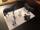
A bit of 3D fun - I managed to download and rescale the horses, they’re really very nicely done. The cow is very clearly a cow, but has a certain air of Kryten, the android in Red Dwarf about her - a bit “faceted”.

The curious lumpy thing is a motor mount & decoder support for John’s pug, thanks to @mickoo for the idea/inspiration.

I’m very pleased with the sack trucks, they’re all my own work. The original was measured on my last trip to Didcot, they’ve come out very delicate, perhaps just a little too much so, but I think I can maintain the fineness without them being quite so fragile. A little subtle thickening won’t go amiss.

image.jpg
 

simond

Western Thunderer
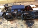
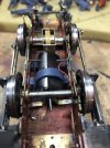
The motor mount in situ in John’s pug chassis.

image.jpg

A very little filing/fitting is required on the lugs that support it, but it fits pretty much straight off. Quite pleased about that too!

image.jpg

And the rectangular plate fits nicely in the hole in the bottom of the boiler so the decoder (when it comes back from Zimo following repair) will be tucked up out of sight.

image.jpg
The loco is running nicely on a PP3 so I think that’s all I can do, pending the decoder. Sweet little thing.

I guess Chris’ pannier is looming…
 
Last edited:

simond

Western Thunderer
Hi Mike.

it’s where the ‘oles are, guv!

the motor has the traditional two fixing holes in the end away from the brush gear, and they are aligned with the holes in the ”ears” of the gearbox, which are horizontal. The motor ends up at that angle. This does mean that the motor can be removed from the gearbox without removing the wheels. I’d have been delighted had that been possible with the Mashima that went pear-shaped, as I had to dismantle the whole chassis to get the motor out. The gearbox does have etched centre points for other screw centres, vertically arranged.

Both motor and Markits 46:1 gearbox from Roxey. The loco was a Springside kit, and has 1/8” axles rather than the usual 3/16” for 0 gauge.

atb
Simon
 

simond

Western Thunderer
Chris‘ pannier was on the “drawing board“ again today, a few minutes‘ calm in an otherwise hectic and somewhat stressful day.

I think it might be possible to stick more or less to plan A by merely elongating the pushrods on top of the axleboxes. More time required to check clearances etc.. Other options are not ideal. Split axles possible but more work, underslung CSBs will show, and my latest cunning plan (CSBs just above the axles, inboard of axleboxes) proved to be more of a stole than a fox on the run. Tant pis, as they say.

Onwards!
 

paulc

Western Thunderer
A bit of 3D fun - I managed to download and rescale the horses, they’re really very nicely done. The cow is very clearly a cow, but has a certain air of Kryten, the android in Red Dwarf about her - a bit “faceted”.

The curious lumpy thing is a motor mount & decoder support for John’s pug, thanks to @mickoo for the idea/inspiration.

I’m very pleased with the sack trucks, they’re all my own work. The original was measured on my last trip to Didcot, they’ve come out very delicate, perhaps just a little too much so, but I think I can maintain the fineness without them being quite so fragile. A little subtle thickening won’t go amiss.

View attachment 201292
Excellent work there Simon .
 

simond

Western Thunderer
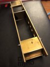
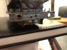
Some metal was cut, folded, and tried in place.

IMG_8454.jpeg

IMG_8453.jpeg

It does look like a CSB solution is feasible, I’m not sure that the frame spacers are right yet, but it has some legs. These spacers are 0.4mm but I might look at using some 1.2 engraving brass for the spacers.

I’m also looking at cutting another set of frames, as if I’m going to do Chris’ loco chassis, I might as well do my own 1361 at the same time.

And I have to cut the slots in the frames for the horns anyway. Not this week!
 
Sand furnace

simond

Western Thunderer
Exciting times, well, a bit…

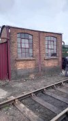
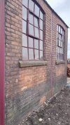
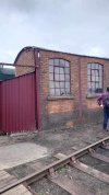
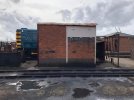
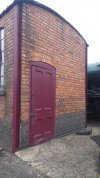
Phil @BrushType4 ‘s Intentio sand furnace arrived and the kit looks great. It’s chilly down here this morning but the sun’s shining so I’ll blat on a coat of red primer and then set about the brickwork before assembly.

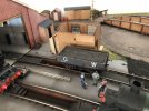
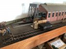
So the question. How were these furnaces used? There’s a door up high on one side which I believe was a hopper to put the sand in - presumably from a wagon, by shovel.

In which case it needs to be near to a track on which the wagon can run, even if it needs to be unloaded and moved out again.

From memory, the one at Didcot is between a shed road and a line along the outside of the shed, I don’t have space for that, but could install it here

image.jpg

Or here

image.jpg

Sadly in both cases, the windows are facing the back of the layout, but I can probably arrange a light or something to shine through them, and add some atmosphere, I hope.

And how was the sand brought out for use?

I recall at Aberystwyth, there were some “watering cans” with big spouts for the sand - were these typical of GW sheds or were they a later VoR addition?

And locos, mmm, @Dog Star ’s search for the perfect guillotine led to @lankytank giving him, and thereby, us, a link to a laser cutting company. I’m going to talk to them Monday about having frames cut to my design.

I’ve had a laser for years, can’t cut brass, and very interested to compare and learn from what Phil can achieve with posh kit and years of experience with my own efforts.

Right, things to do!
 
Top