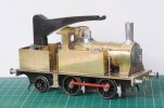
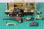
The Heybridge Railway, 1889 to 1913

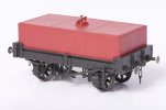
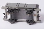
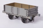
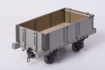
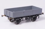
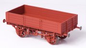
Drop-side wagon (mid-1870s style)
  • Richard Gawler

    Western Thunderer
    Thank you all for your kind comments.

    This is my second wagon (my first is a bit dull), this shows quite a bit about where I am in the hobby at the moment:


    The prototype is not well know, if it ever existed; but there is evidence of origins to those in the know. My railway layout (not started yet) will be a might have been, and I think its service vehicles should be might have beens as well.
    I can cut parts so they fit together (no filler in this build) and I can apply a simple coat of paint from a spray can but my hands shake when I try to paint in details.

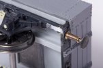
    I reach a stage of impatience when my models are nearing completion and so the coupling links are unsoldered because I wanted to do something else. The buffers could have been a millimetre shorter for coupling up on Setrack curves but I had to build one wagon to find this out. Nevertheless, I set up the wheels in their bearings about right, they spin freely without side play and the model sits flat on a flat bit of track.

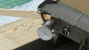
    I am not feeling remotely photogenic at the moment so the end of this wagon can be my avatar to begin with.DSCF2416.jpg
     
    Last edited by a moderator:
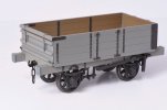
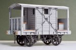
    NBR box van (1893)
  • Richard Gawler

    Western Thunderer
    DSCF2467.jpg

    This is my take on the Peco/Parkside kit for a NB van. The parts for this were incredibly cleanly moulded and there is no filler in the model, though the photo suggests a scrap of filler behind the buffer headstock would be good. A friend told me about Microset and Microsol and this is my best ever attempt at putting on transfers, I feel they really do look like they were painted on. The paint is Halfords grey primer with Humbrol satin enamel varnish on the top, and the brake lever is posable.
     
    Break van (c.1870, ex Mid-Wales Railway)
  • Richard Gawler

    Western Thunderer
    The first break van for the H&LLR comes from the Mid Wales Railway. The prototype worked there before becoming the chief engineer's vehicle (saloon?) on the Elan Valley dam project. It could do the same roles for me; an early break and let it be superseded by something more modern like the Slaters MR van in Edwardian times.

    DSCF2719.jpg

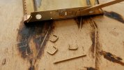
    This is a laser-cut MDF kit by Sixteen Mill. I struggle with some of the parts and you can see where the wood split trying to do the hand rail bottom right. The roof structure was a completely new, from strip styrene. The wheelbase is only 7 ft 6 in so it sort of looks the part.
     
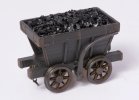
    Chaldron wagon (1860s design, 1880s build)
  • Richard Gawler

    Western Thunderer
    DSC_9321.jpg

    I built my chaldron wagon before my break van and it got out of sequence because I wanted to try out my new camera. This is a Nikon D7200 from Cameraworld in Chelmsford who guided me towards a sensible secondhand replacement for my ageing Fuji s5 Pro. The new camera seems to cope with near-blacks (very dark greys) and black and white rather well.

    I am still pleased with the wheels on this, I tried quite hard because they are so conspicuous.

    The Surrey Iron Railway had wagons similar to this, the basic shape is not exclusive to the North East and I thought my railway could acquire one so a horse could move small quantities of coal around the place.
     
    GER Lomac (1913 - used during dismantling the railway)
  • Richard Gawler

    Western Thunderer
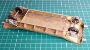
    I was professionally trained how to solder ... but for electronics assembly work. I took me ages (a lot of years) to find the courage to try an etched kit. I watched a demonstation of kit building at a show, and then three modellers independently told me to try a Jim McGeown kit, "I would be perfectly able to do it". The important thing then was to totally un-learn the golden rule for electronics assembly; you really do have to put the solder on the iron and take it to the job - pretty much equivalent to writing your own P45 for electronics work.

    I began with what I thought was a 45W soldering station and had trouble. The received wisdom was to use a 40W Weller with a bit like a screwdriver, but seeing the trouble I was having I bought a 60W Weller. This finished the main assembly but I spread solder all over the place underneath - the bit was 6 mm across. Two days on this iron packed up. The LEDs lit up but no heat. I took a closer look at my soldering station and saw that while the base unit was 45W (well, 45VA really) the iron attached was rated at just 20W. Well that explained a lot. I went to Screwfix and bought a 40W iron by CK. A most helpful discussion with Jim confirmed this CK iron is really a re-badged older-style Weller.

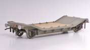
    I chose the ex-GER Lomac L. The idea at the time was to pretend these were built a few years earlier than they were (to fit them into the second decade of my time frame) but realistically, the model is better used for me to represent the dismantling of the railway in 1913. I will assume the GER refused to allow the ancient dumb-buffered wagons to travel on their metals and insisted on carrying them out one by one.

    P1040134.jpg

    The hardest part was the lashing rails for the ends. I broke the brass wire three times before I tried round nose pliers and then I formed the rails to the wrong length. I ended up with c.15mm wire left over so full marks to Jim for providing enough material to allow for some mistakes. But really, these were horrid to make up. Hurting fingers.

    P1040138.jpg

    The rings themselves are soft copper wire and really easy to make (wrap wire around a small drill to make a spiral, then snip off individual rings) but soldering them up so they were "articulated" was like nailing jelly to a tree. After sleeping on this I settled on a bit of wood to jam them and hold them steady and suddenly they were easy too.

    Studying this photo I think my rivets are a bit pointy and I need to back off the setting on the embossing tool (I bought the one from the Midland Railway Centre).

    Looking back, my soldering wasn't all that bad. I tidied it up quite a bit with the CK iron before I put the paint on.

    DSCF3291 (1).jpg

    I am missing a suitable photo but the wheel bearings have to be set slightly inboard of the brass chassis. I fixed one with cyano, propped the wagon on its side, and then soldered the other bearing. Then turned the wagon over and soldered the first bearing. Gravity holds the axle and bearings nicely, the wheels spin freely but there is no unwanted end play. Then the axle box castings went on with Araldite.

    DSCF3342 (1).jpg

    The level of satisfaction after building this model just left me wanting to do more.

    PS I have edited this a few times because I am still getting the hang of the editor.
     
    Last edited:
    Tender truck (assumed new in 1889)
  • Richard Gawler

    Western Thunderer
    Vallejo is amazing. I have only tried two bottles so far but the results were really good. The timber deck on the Lomac is Vallejo, applied with a flat brush and it just "worked".

    I would like to move on to my second brass wagon build, I have a load of photos of the build. I will try to post the first batch of these tonight, this seems sensible because I have a fresh kit to build next weekend.

    DSCF3360.jpg
     
    Last edited:
    NBR 'Jubilee' coal wagon (1887 style)
  • Richard Gawler

    Western Thunderer
    DSC_9382.jpg
    This is a North British 'Jubilee' coal wagon from the Peco / Parkside kit with the solebars exteded to make dumb buffers.

    DSC_9380.jpg
    Some of my wagons get painted underneath and some do not. The ballast weight is 2 mm roofing lead.

    DSC_9385.jpg
    I was pleased with the end door. I put a scrap of paper under the bottom edge when I glued it on to leave a tiny gap and it does look like a door and not a fixed end with hinge details.

    DSC_9386.jpg
    I painted the model with Revell enamel no.43 "USAF Gray" because I had some of this to hand. The ironwork is Tamiya 'Dark Iron' and the inside walls are Humbrol 'wood'. The floor is a laser-cut panel from Poppy's Woodtech and this is still unpainted at the moment.
     
    Last edited:
    GWR Hydra (1908) . . part 1 build
  • Richard Gawler

    Western Thunderer
    40W might be a bit light for 0 gauge models, but much will depend on the mass of the bit.

    I must have missed this bit first time round. :rolleyes:
    I would venture that there are some things that might be "too simplistic" for WT - pictures of how to open an R-T-R box*, maybe - but NOT soldering & building etched brass, however basic or advanced the kit involved. ;)

    Thanks . . . this gives me a prompt to slip from "Blue Peter" mode (where I have been since I started this account) into what is on my bench at the moment . . .

    DSC_9454.jpg

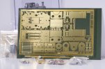
    This is Jim McGeown's GWR Hydra. The mass of brass here is about 45 g and the mass of the bit 12 g. The soldering here involves connecting two lengths of deck together end to end, laminating two pieces of side together (the second layer is hidden in this pic), and attaching the side to the deck.

    To my mind, the 40W iron is fine to put all of these together, but I had the very devil of a job undoing two of my four bits of "spot tacking" after I put the side on with a gap between itself and the sloping deck. Quite difficult really; a prolonged application of the iron, a Stanley knife blade pushed in really hard and, eventually, freedom. The obvious solution is to make smaller tacking blobs and to look at what I have achieved after each blob, not after the fourth.

    With the tacking done, the 40W iron is making enough heat and carrying enough solder to the job to let me solder up c.20 mm of seam at a time. I now have two bits for the iron: the original one, which is like the tip of a flat screwdriver, and a conical one, which tapers to a radius of perhaps 0.5 mm. I prefer the conical one because it lets me spread a narrower path of unnecessary tinning each side of the seam. I am putting the flux on with a budget brush, five for £1 from The Works.
     
    Last edited:
    GWR 4-plank wagon (1880s) . . part 1 build
  • Richard Gawler

    Western Thunderer
    I am also building a GWR 4-plank wagon, this is from the Slaters/Coopercraft kit.

    DSC_9340.jpgDSC_9346.jpg
    I had some trouble getting the solebars to meet up with the headstocks, and then more trouble getting the filler to stay put. So I added some scraps of styrene across the joins and then rubbed these down so they were like paper. This seemed to tidy things up.

    DSC_9365.jpg
    The brake gear is from a Minerva Iron Mink which I am back-dating from BR to 1890s condition. This is a finer moulding than the Slater's one. Also, I knew where to put it onto the model; I couldn't get my head round the Slater's instructions.

    A friend has lent me a copy of 'GWR Goods Wagons' by Atkins, Beard and Tourret. Looking at plates 349 and 350, I have a feeling the door springs need to go. This is what happens if you make a model by copying someone else's model and then get the prototype information.

    "I expect there are other mistakes I could try to put right if I knew what they were" (suggestions welcome)

    I can't believe I have only been here three weeks, I think I will be happy here.
     
    Notes on railway loco and wagon technology
  • Richard Gawler

    Western Thunderer
    Railway wagon technology
    This is a small ‘editorial’ post to write a bit about the purpose of this model railway project.

    I bought a Manning Wardle ‘K’ class loco, a RTR model by Minerva Models. I rather admired the model, and eventually I bought some track and saw how well it ran. I experimented with different controllers (feedback and non-feedback) and settled on a feedback one from All Components. I sought out reviews of the model and the first one I found said this:

    “There's something quite Wacky Races-esque about the nature of the prototype locomotive - its token cab with exposed sides and small spectacle windows, combined with its flared coal bunker and small finescale wheels are humourous in design, but beautifully-captured”.

    And I thought, I do not believe what I have just read, I am going to find out about the technology which went into this loco. Manning Wardle built this design for sixty years, what made it so good?

    The result was a list of features, which I am uploading here (pdf file) so maybe I will not be the only person who ever reads it.

    It struck me, the design development of the steam locomotive was already almost complete in terms of its features, but rolling stock had a long way to go. A Victorian wagon might last 15 years (depending on what it was used for); so if I built a layout set in the 1890s then an 1887 RCH design would be the state of the art and there would be plenty of older designs with dumb buffers to make up a mixture.

    The 1890s seem to be rarely modelled, and the mainstream kit manufacturers start their ranges in the 1910s. These are more modern-looking wagons. I want to build some these to gain skills and confidence before tackling older designs. And so, I can try to represent a small railway as it might have appeared over 20 years, a period when railway wagons grew bigger, gained continuous brakes, and more were made from steel instead of timber.

    This approach ought to let me possess (and of course build!) a few dozen wagons and choose from these a handful to run at any one time. I already have four wagons from the GWR, but this isn’t quite as absurd as it sounds because only one or two will ever appear during a single operating session. Other wagons can get new roles, for example the ex-Mid Wales break van can be superseded by something more modern and be re-appropriated to become the chief engineer’s personal vehicle (this happened to the prototype). Some of the wagons that arrived here carrying long-distance traffic in the early years can be bought and owned by the railway for service use during later years.

    Well this is the idea. It probably sounds a bit academic as written up here but if I draw a line at 1913 and work backwards to the 1870s I ought to be able to create a pleasing sort of variety, and if I build one wagon per month (ten done since last October) I can be busy for years. The layout will be a maximum of 11 x 2 feet (the design is still a bit loose to post here), so perhaps six wagons in operation at a time.
     

    Attachments

    • The technology of the MW K class locomotive.pdf
      142.9 KB · Views: 33
    'Blackwater' - a Manning Wardle 'K' class (1888)
  • Richard Gawler

    Western Thunderer
    I am imagining, the H&LLR company engaged the services of T A Walker contractors to build the first stage of the line from Heybridge to Langford, and construction started in 1888. Walker’s had substantial experience of railway work from their efforts on the Manchester Ship Canal, and brought with them a Manning Wardle K class locomotive to do the work. The locomotive was MW works number 1032 built in 1888. The locomotive worked the line until closure, when it was returned to MW, refurbished and exported.

    The locomotive Works List for MW shows 1032 was a K class, was named ‘Thornton’, and was exported to Buenos Aires. I am simply giving the locomotive a bit of imaginary domestic use before she went to South America.

    DSCF2549.jpg

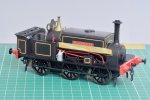
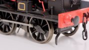
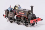
    ‘Blackwater’ is my Minerva K class. She has a weatherboard and tools supplied by the manufacturer, real coal in the bunker and a little brown paint on her brake blocks. Her crew are from ModelU, I know this is a constructive hobby but I indulged in sub-contracting out the figure painting to Dan Evason of Tunnel Lane. The name and works plates are by Light Railway Stores (who I still want to call Narrow Planet) so arguably my creative input so far has been in choosing the height of the name plates.

    DSCF2947.jpg

    DSCF2400.jpg

    I darkened the wheel treads with gun blue, the effect is smaller than with using the same chemical on Slater’s wagon wheels but is I think still worthwhile.

    ‘Blackwater’ runs perfectly on my analogue controllers. I have a simple Gaugemaster controller and a feedback controller from All Components and both work fine. Her only vice so far has been to undo and drop the screws serving as crankpins on her centre wheels. Fortunately this has happened on tracks without ballast. After the second episode I secured these screws with Loctite 601, this is a green retaining compound marketed as ‘permanent’.

    The crankpin screws are tiny. I ‘made’ a nut spinner for them by squashing a bit of brass tube in the vise. This worked so well I added a bit of plastic tape afterwards so it looks like a tool and not a bit of scrap.

    DSC_9610.jpg
     
    'Nellie' - an 0-4-2 crane tank (assumed new in 1905)
  • Richard Gawler

    Western Thunderer
    I want to build a Connoisseur J15 and I am working my way up through a food chain of brass kits, savouring new skills and changing my expectations of what a kit can give me.

    DSC_9540.jpg

    I received a Connoisseur starter loco kit for my birthday, and I have bought the motor and gearbox to go with it. I will buy the wheels when I have made some progress.

    And then I thought, how about a crane tank? This will be more useful than a Nellie/Polly and it will tie in with E H Bentall having their own foundry. I have a spare packet of Lomac wagon wheels, so how about extending the footplate behind the boiler, making a new bunker to hold the jib, and turning the loco into an 0-4-2 crane tank without a cab?

    I have made a start on the loco by assembling the brake blocks onto their hangers, assembling the steps onto themselves and painting the name plates. I am now assembling a crane bought separately from Gladiator Models. When I have the crane jib assembled then I can see how things might look.

    This will be, of course "Nellie the Elephant".
     
    . . useful photos of Mike's crane jib
  • spikey faz

    Western Thunderer
    View attachment 165695

    My completed crane jib.

    This is my fourth brass kit, the first three were wagons. The jib is not terribly difficult to assemble, the hardest part for me was working out how to hold the parts togehter for soldering. I am tempted to buy a leather glove for the holding hand.

    I did find the instructions to be a bit challenging so if forewarned is forearmed . . .

    The jib has two sides and four covers: underside, top, rear and front. The covers go on in this sequence, so the front/back alignment of the underside dictates everything that follows. The instructions for the underside:

    "This part should be fitted . . . starting level with the vertical front edge of the jib"

    1. I began by forming a radius on the broader end of the underside so it would sit snugly against the front of the side frames, and soldered this part into place. So I used up about 3 mm of the length of the underside going around a curve to reach onto the vertical edges. The instructions don't mention a radius, but it worked.
    2. I added the top cover, the narrow end of the top cover aligns with the narrow end of the underside.
    3. I added the rear cover, beginning at the bottom and working upwards and then over the curve at the top. I ended up finding the rear cover was about half a millimetre too long, so it was easy to trim the broad end of the top cover and everything fitted perfectly. Beginners luck I am sure.

    View attachment 165697
    The front cover has to be formed into a semi-circular shape. I think life would be easier if this cover was a millimetre longer and I contemplated making a new part. I anealed the front cover to let me form the curve and life would have been easier still if I had done this before starting to form the shape and not part way though when I realised it was too tough to get into the proper shape. My attempt at a semi-circle is a bit rough but no-one will look at it from underneath.

    My biggest failing on the jib was to solder it up with a cross-section like a parallelogram and not a rectangle. I noticed this too late to put it right. It is the sort of job I know I would do better next time . . . I have a feeling it won't show up unless I put a try square agianst the side of the jib on the finished model.

    I took most of four hours to put the jib together! I am sure Rob will do it in less.
    Mine went a bit banana-shaped as well! Rather than unsolder it all, I used a bit of brute force to 'tweak' it straight. I think you're right in that unless you try a square against the side you'll never notice!

    20220623_112645.jpg
    Mike
     
    . . construction
  • Richard Gawler

    Western Thunderer
    DSC_9650.jpg
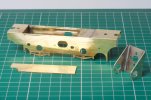
    The chassis seems likely to flex quite easily so I have reinforced the top edges with scraps of fret. These also fill in the excess width to make the motor mount a snug fit. I am waiting until I get the driving wheels before I decide on the position of the trailing axle.

    DSC_9657.jpg
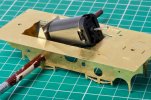
    There is plenty of space for the motor, but I would be happier if I could have it closer to the horizontal. This would make space above for a DCC socket, decoder and possibly a sound installation one day. The motor is resting on a frame spacer which I want to retain because it includes a slotted hole to arrange a rocking front axle.

    At the moment I have a 1833 motor. I wonder, is there a shorter motor which fits the same mount? Controllability is important but power is not; if the loco can haul eight small wagons this would be fine.
     
    ( Diversion : LNER Y7, post-dates the railway )
  • Richard Gawler

    Western Thunderer
    DSC_9667.jpg

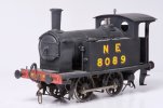
    8089 had not enjoyed her journey to Essex. It was bad enough saying goodbye to all of her friends at home, but then being wrapped up and sent as a parcel was just an insult. Whoever heard of an engine travelling by post! The whole point of being an engine, and a standard gauge one at that, was to be able to run on rails. The only saving grace so far was some muffled talk in the Post Office about “special delivery”. Certainly, the journey had been swift; barely a day. She thought for a while and conceded, it would have taken her quite a lot longer to drive herself there.

    8089 sat on the track. No ballast and a load of paint bottles in the six foot. Clearly there is a lot to do in this place, but at least things can only get better. Her new owner seemed to be careful if a bit thick. He had unwrapped her gently enough but he didn’t seem to have much of a clue about her 21st century control gear. He tried to address her as “8089”, which was stupid (whoever uses the whole number for an engine?) then “3”, which was worse. “3” was for visitors, and was never used for a Retained Engine! Then he tried “8”, which he had seen on the label below her cab, and she could to move.

    She trundled up and down the line until, from the sky, appeared a tender truck. A tender truck, just like the one she had in the North East! Her owner couldn’t see here face, so she gave a big wide smile while he wasn’t looking.

    The tender truck was at the very end of the running line, and she ambled towards it and buffered up, smokebox first. “I wonder what will happen now?” she thought. There isn’t a run round loop here, and if he thinks I’m up for fly shunting on my very first day he can forget it. And then, her owner picked up the tender truck and put it back on the rails behind her! Suddenly, she knew she would be happy here. This wasn’t one of those ‘finescale’ operations where engines aren’t allowed to go racing or talk to each other between turns. This was a proper home layout.


    “8089” is a NER Y7 someone has built from the Connoisseur kit. She represents a locomotive modified for the North Sunderland Railway, and has a gearbox with helical gears and two-stage reduction, and a DCC decoder. Possibly she has some kind of stay-alive too because she crawls over my Setrack point with the unifrog disconnected without hesitating at all. She might become the passenger train loco on the Heybridge Railway, or I might imagine ‘Blackwater’ departed to South America sooner after the line opened. She needs a name, so far only ‘Blackwater’ and ‘Kingfisher’ are taken.
     
    . . construction
  • Richard Gawler

    Western Thunderer
    DSC_9691.jpg
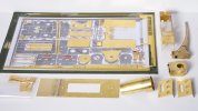
    Before I started the 'Nellie' I put the fret in the scanner and printed out a copy to hold loose parts (Sellotape). The print is a bit undersize but it has worked out ok. The red pen shows really small parts (and parts I think I don't want) removed and put into a plastic bag. I have extended the footplate by 1 1/2 inches (this will become an 0-4-2) and trimmed the cab and its roof to make a half cab.

    This photo is a bit of a milestone as there is nothing left to do except actually try to build the model. So, if it all turns out to be a bit of a disaster it will at least be an organised disaster.

    Yesterday evening I caught the front buffer beam on the buffing wheel, folding it in half. The scan was a good idea but I wish I had included a steel rule.
     
    . . boiler fittings and crane detailing
  • Richard Gawler

    Western Thunderer
    I eventually found the lost crankpin bush (brown on a brown carpet), dropped a 12 BA nut and found another one dropped a while ago. I can think of a good if non-engineering reason to go for 10 BA crankpins next time.


    DSC_0040.jpg

    I wrote to Jim Mcgeown with an order for a new kit and to ask whether he could supply a stovepipe chimney and a Ramsbottom safety valve for Nellie. The castings arrived yesterday, free of charge. The service and quality from Jim is consistently superb.

    Now, I have a feeling these parts are for a loco one or two sizes bigger than Nellie (they are from his J15) but I think they provide a dose of character the model has really needed.

    I had already moved the whistle (originally in the middle as post 217) to make room for the safety valve, little knowing the Ramsbottom design has the whistle as an integral part. So Nellie is going to get a second whistle. I don't know whether crane locomotives actually had such a luxury but one note for the loco and a different one for crane operations sounds reasonable to me. And doing this will stop the spectacle plate getting like a piece of Swiss cheese.

    I have just broken off the handbrake handle.
     
    . . major sub-assemblies of the completed model
  • Richard Gawler

    Western Thunderer
    DSC_0068.jpg

    One final photo of Nellie to show the subassemblies I mentioned in post 235.

    The pivot pin ended up being soldered solid onto the base for the crane, apart from this little changed from how I saw things then. This is as far as the model can be dismantled, apart from changing the wheels or motor or similar.

    I have used BA screws to attach the chassis to the body and a metric screw for the trailing axle. They look quite similar at a glance. I would rather not do this again, I need to buy a few BA taps.

    I have soldered the two rear sand pipes onto the body. I won't do this again either, they leave the body needing blocks of wood or similar to stand it on the workbench. Some brackets on the chassis would be better.
     
    Top