The Heybridge Railway, 1889 to 1913

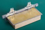
Four-wheel saloon - body, solebars, floor and roof
  • Richard Gawler

    Western Thunderer
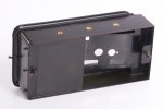
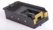
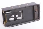
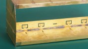
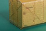
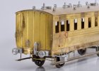
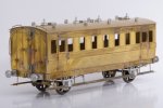
    My next project is a 4-wheel saloon coach from a kit by Connoisseur Models. This is my first attempt at building a coach kit. I have tried to modify RTR coaches e.g. cut and shut and even new sides on RTR in smaller scales, none with much with success so hopefully a purpose-made kit will work out better.

    I am not sure whether my Heybridge Railway actually needs this coach. It might be there to supplement the brake coach for fair days and market days. I want to build the brake coach with fairly heavy modifications of the source kit so some practice will be good. If I don't want the saloon, or the layout just cannot be big enough to hold a two-coach train then I can treat it as a learning kit to sell on after completion.
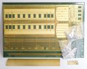
    DSC_2446.jpeg
    The kit comes with a prerolled roof, good because I don't have any rolling bars and the roof is going to be conspicuous on the finished model.
    I bought the kit at Kettering on 5th March, it is secondhand but unbuilt so a modest cost saving over buying a new one.

    Work begins by forming the sides, beginners luck maybe but this these turned out pretty well.
    DSC_2481.jpeg
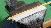
    I don't have any folding bars either so I formed the tops of the sides in the vice. There is a half-etched bend line and I scored this very heavily using a scriber, and then worked the flange over I suppose about 15 degrees at a time. This is not ideal because it tends to stretch the narrow strip of flange. Afterwards I worked the flange down onto a piece of plywood from an old drawer unit (nice square edge) and the ripples have pretty much vanished.
    DSC_2447.jpeg
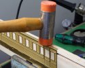
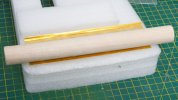
    The newest additions to my armoury are an offcut of hardwood dowel and a piece of dense foam. This is the sort of shiny rigid foam which comes in blocks formed by layers bonded together. Anyway, I formed the turnunder by pressing the dowel into the side. I didn't roll the dowel very much. I doubt this approach would work on a mainline coach but on this one the results just came out perfect first time.
    DSC_2453.jpeg
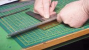
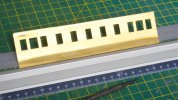
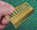
    Working the fold for the flange at the bottom was more difficult than the turnunder but easier than the flange at the top. I am holding the flange flat onto the bench with the straight edge whilst lifting the side with the steel rule.
    DSC_2448.jpeg
    Part way round.

    DSC_2460.jpeg
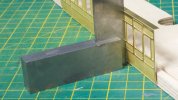
    Bonus picture because I had a visitor and they held the camera. I am shoving the flange into place with the back of the square.
    DSC_2484.jpeg
    Result :)

    DSC_2462.jpeg
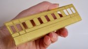
    Hopefully this photo shows the shape created using the bit of dowel is actually pretty good.

    Small thought:

    When I was writing technical publications for a living we decided to exclude tools and body parts in photographs. The only exception being the use of a tool in an unconventional way e.g. using a using a screwdriver to prise off a blanking cap. Having a distant and impersonal look is fair enough for system build and maintenance manuals (and the only practical way if you want a consistent hand in the photos) but maybe it brings a bit of life to a workbench topic?
     
    Last edited:
    ( Diversion : Nellie visits the Middy at Debenham )
  • Richard Gawler

    Western Thunderer
    Nellie visits the Middy.

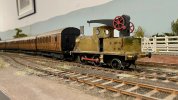
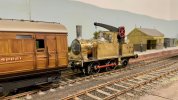
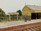
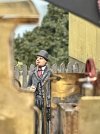
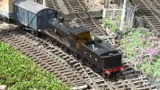
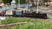
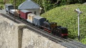
    The history of the Heybridge Railway records that Nellie the crane tank was destroyed during the Zepellin raid of the night of 15/16 April 1916. The "might have been" scenario here depicts the arrival of Nellie at Debenham (this was, of course, on the extension of the Middy) and captures the reaction of a passenger waiting at the time.

    WhatsApp Image 2023-04-10 at 13.40.28.jpeg

    WhatsApp Image 2023-04-10 at 13.44.41.jpeg

    WhatsApp Image 2023-04-10 at 13.45.19.jpeg

    WhatsApp Image 2023-04-10 at 14.07.59 (1).jpeg

    Photos by Tony @Osgood
     
    Last edited:
    . . part 2 - wheels, brakes and minor details
  • Richard Gawler

    Western Thunderer
    Wheels and brakes.

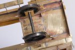
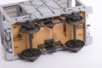
    The wheels are running in sprung suspension units, these units are also from Connoisseur Models.

    DSC_2615.jpeg
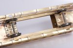
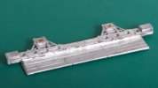
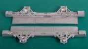
    I seem to have stepped in something when I made the two sections of floor. These are offcuts of 2 inch wide brass, trimmed to fit the width of the model. The tops of the suspension units align perfectly, this was not by my design.

    There was an option to fix the suspension units with screws and nuts but the fixings would get in the way of a cosmetic floor so I didn't try. It would be easier to hide the nuts in a compartment coach.

    DSC_2621.jpeg
    The kit has eight brake hangers and I have doubled these up to make the four on the model so they look more substantial. One of them seems to be delaminating. At the moment, the springs are 0.015 inch piano wire. These are stiff enough to hold the coach, minus its roof and castings, at its maximum ride height.

    I have done some trial runs by propelling the coach along my test track and running is really good including through my usual Setrack reverse curve. The body doesn't show a tendency to wobble, which I was half expecting having put a spring on each corner.
     
    “Heybridge, an Essex Idyll” (the back story)
  • Richard Gawler

    Western Thunderer
    “Heybridge, an Essex Idyll”

    (The Heybridge Railway, 1889 to 1912)


    Foreword​

    The model railways I enjoy the most are the models of “might have been” schemes and I have now found enough ideas to start building one of my own. I am beginning with the trains, the layout can follow later.

    This is the story of the Heybridge and Langford Light Railway as it might have been in rural Essex, serving the industries and populations of Heybridge and Heybridge Basin during the late 19th and early 20th centuries.

    The chapter of “Historical Background” in Part 1 of this account is true; the rest is fiction.

    2-56160.jpg
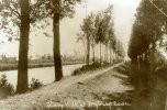
    The supposed route of the railway beside the navigation, photographed in the 1930s


    Contents​

    1. The story of the Railway

    2. Traffic and Traction

    3: Closure and Legacy

    4: Representing the Railway in a Model

    Appendices (these are under development and very detailed, so available on request)
    Appendix 1 Timeline
    Appendix 2 Traffic and Traction
    Appendix 3 Train Formations
    Appendix 4 The Technology of the MW K Class Locomotive
     
    Last edited:
    Break van (c.1870, ex Mid-Wales Railway) part 2 - refurbishment
  • Richard Gawler

    Western Thunderer
    My ex-Mid Wales Railway break van has never run particularly well. It was adequate on my test track at home but it didn't cope very well on layouts where there is a minor sideways step between the rails at baseboard joints. This was because most if not all of the wheels were not square on their axles, so the B2Bs varied as the wheels went round.

    So I have reworked the wheels, putting them onto new axles and arranging them in some suspension units from First Class Kits.

    DSC_2635.jpeg
    This photo is simply how I originally built the model. The wheels were supplied with the kit (SixteenMill kit) but not fitted on their axles and I expect most of the problem came from me being unable to press them onto the axles squarely at the time.

    DSC_2640.jpeg
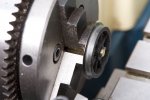
    I now have a lathe. I cut new axles from some 1/8 inch brass rod, and bored out the wheel centres to suit. The rod measures 0.125 inch diameter, the shank of the drill bit measures 0.123 inch but I still ended up with a fit slightly looser than I really wanted. So I put some CA glue into the wheel centres and pressed the first wheels onto their axles using the tailstock spindle. Starting the motor, these wheels actually ran true.

    DSC_2682.jpeg
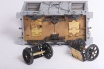
    The wheel carriers fold up from a brass etch. I pressed on the second two wheels between the face of the chuck jaws and the tailstock spindle, this wasn't quite so effective. I still have a run-out on both pairs of wheels (about 0.1 mm) but this is a lot better than whatever was there when I started.

    DSC_2684.jpegThe wheel carriers block the spaces for the springs and split pins on the coupling hooks so the hooks are now secured with epoxy glue.

    DSC_2693.jpeg
    Back in service.

    When I push this model along the track by hand, finger tips gently pressing down on the roof, I can feel a slight eccentricity somewhere. I expect, my school metalworking teachers would be telling me to use the four-jaw chuck and set it up properly to hold the wheels for boring out the axle holes, and not the self-centring chuck. However, the wheels are more orthogonal on their axles now. I will find out the result on the next trip to the club layout.
     
    Last edited:
    Charlie (a sort of 0-B-B-0)
  • Richard Gawler

    Western Thunderer
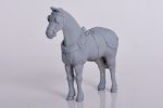
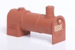
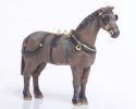
    After all of the problems I had with the stationary boiler from Duncan Models I have assembled a light delivery horse from the same source.

    DSC_2733.jpeg
    This is two whitemetal castings plus detail parts, and the parts fitted together with only a little filler. There was hardly any cleaning up to do either, much better.

    Painting is another matter for me, this is going to get subcontracted out.
     
    Last edited:
    Stationary boiler . . completion (or controlled abandonement)
  • Richard Gawler

    Western Thunderer
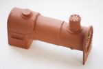
    I have called time on the stationary boiler. This is a personal first for me, a model which looks better in photographs than in real life :confused:

    DSC_2737.jpeg
    Natural daylight shows up plenty of flaws. I could file off all of the rivet detail and say "less is more" but despite my efforts the boiler is too far away from being cylindrical, it looks awful.

    DSC_2754.jpeg
    Diffused light helps. I now have a pile of wooden cocktail sticks without ends.

    DSC_2752.jpeg
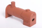
    The backhead looks fair-ish but I forgot to thin the metal around the firing hole (see post no.701), I can hide this with a board to keep the rain out.

    My big lesson learned here is, a scenic model has got to be just as good as a loco. In retrospect, if this kit had been for a loco I would have posted it back and asked for a refund - the details are wrong, the instructions are wrong, the boiler parts were heavily distorted and the firebox parts were too small to reach each other. The only parts I am proud of are the filler, the main steam pipe (which I made myself from brass) and the paint job.

    This is the first time I have tried U-Pol #8 primer on whitemetal. I left it overnight and it seems to have stuck and not reacted with the top coats. I suspect Halfords grey primer would have worked just as well. The "red oxide" is Humbrol enamels no.70 brick red with a large dollop of no.100 red-brown, two coats sprayed 30 minutes apart to try to let them merge together.

    So - a model to include as a wagon load in a carefully-composed photo but not to enjoy very much let alone glue down onto a layout. Unless, as Tony (@Osgood) suggested, I cover the whole thing in a large tarpaulin :thumbs:
     
    Last edited:
    Bentall-style IC engine
  • Richard Gawler

    Western Thunderer
    E H Bentall built numerous small internal combustion engines so I have built the kit by Duncan Models to represent one. This is the last of the three kits I bought from this firm at Kettering earlier this year.

    I think I have made more posts than I have really needed (like the roof of the coach) so here is the build of one kit all in one post . . .

    DSC_2756.jpeg
    The kit cost just £4.50, I thought this was most reasonable and at a glance it seemed to have potential for improvement so a good buy.

    DSC_2760.jpeg
    Both flywheels had flash but this one also had a shortfall of metal.

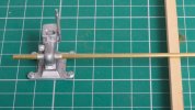
    DSC_2770.jpeg
    Blob of 145 degree solder to fill shortfall. Casting bored and tapped, and mounted on a 6BA bolt as a mandrel, then dressed to suit.

    DSC_2783.jpeg
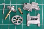
    All parts prepared before final assembly.

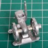
    The cast bosses provided on each side of the body to hold the flywheels were a bit approximate so I cut them off completely and drilled through the casting from side to side. I also remembered to drill a hole to hold the exhaust. The exhaust casting is unchanged.

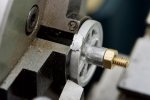
    I bored out the bosses of both flywheels 1/8 inch and pressed in short lengths of brass tube. Their axle is 3/32 inch rod and this will run in the loose piece of 1/8 inch tube. I put a slight flange on the pulley so any drive belt is more likely to stay put and not fall off.

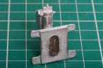
    The body casting had two prongs to aid fixing but these didn't line up with the holes in the base so I cut these off too. I added the loop of wire to catch with some glue, and opened up a generous hole in the base. This hole was a bit too generous and the photo shows two the scraps of solder I added and filed down to hide the gap.

    DSC_2788.jpeg
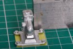
    I placed the base on a piece of masking tape, filled the hole about three-quarters full with epoxy glue, and placed the body into position. Some Dark Forces went to work to pull the casting clockwise in the runny glue so I added the square to hold things in place.

    DSC_2798.jpeg
    The epoxy dried clear and has run around the loop of wire.

    DSC_2802.jpeg
    Bearing tube fixed into place with 100 degree solder. I now have a spare bit for the iron, dedicated to use with low temperature solder. I used this length of rod to check the bearing tube for a square assembly when I tacked it in.

    DSC_2805.jpeg
    Simple things amuse simple minds and I can amuse myself by spinning the two flywheels.

    I have seen Bentall's products (in 2022 and 2023) finished in bare cast iron and painted pale green. I am confident the pale green is authentic but I would like to find out when it came into use before I paint the model.

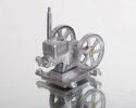
    DSC_2818 (1).jpeg
    Indulgent final photo, this was fun to build and I am pleased with the result:drool:
     
    Last edited:
    Mixed trains and a possible fiddle yard
  • Richard Gawler

    Western Thunderer
    I have identified my first really Stupid Idea for the project so far. By stupid, I mean taking time and expense and effort on my part and bringing no benefit to me, anyone else or the the project as a whole. This concerns the coaching stock.

    1. The original idea was to give the Heybridge Railway one brake third coach to handle all of the passenger and mail services in a compact formation - a sensible idea.
    2. I made an impulse purchase of the saloon coach, "to give me practice and make a longer train for special days" - a good idea at the time.
    3. I decided to build the brake vehicle as a private coach and this would run with the saloon to make a public passenger train.

    The upshot of this is, as soon as the private saloon leaves the railway on its travels to distant places, I cannot run any passenger trains because I won't have a brake vehicle for them.

    :headbang:
     
    Painting highlights and shadows
  • Richard Gawler

    Western Thunderer
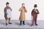
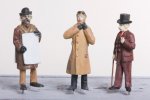
    I have had a first go at painting figures in 7mm scale. These are two white metal ones from Omen Miniatures (bought though eBay from France!) and one of unknown origin. This has taken me a few goes so here are two photos.

    DSC_2902.jpeg
    I thought I had finished them. I was happy with the shading on the clothing but the faces and some details looked really ragged.

    DSC_2909.jpeg
    Take two.

    I had a couple of goes putting on the lipstick but the layout needs a few really tiny anachronisms for those who are paying attention.

    The main thing for painting them was to imagine the sun is immediately above the figure, and paint on highlights and shadows to suit. I saw this method on a video for painting Warhammer. I had a lot of goes at the the face of the sandwich board man and then all of a sudden the dark wash seemed to sort it out. His message remains to be decided but perhaps "ROYAL VISIT" or "MORE DRIVER MENACE".
     
    GER Y14 - assembly after painting
  • Richard Gawler

    Western Thunderer
    DSC_2353.jpeg
    To recap slightly, this is my Y14 and its tender on 15th March this year. I bolted the subassemblies together before sending them off to Warren for painting.

    I have now completed the subassemblies for the tender, so here are some photos of this activity.

    DSC_2978.jpeg
    The r/c speed controller has no output protection. A dead short across the motor terminals is Unlikely but if I fit a fuse and it never blows I will have some peace of mind.

    DSC_2983.jpeg
    As an apprentice in the 1980s, machine screws were not only still used, but were tightened so the slots matched up.

    DSC_3007.jpeg
    I like this palette of black and bright metal with red highlights and it is going to continue thoughout the model.

    DSC_3020.jpeg
    Warren asked me to leave the axleboxes and springs off the footplate assembly to make his lining task easier. I have now put them, I used epoxy glue straight on top of the paint.

    I found some daylight between side frame and fooplate. I suppose, I never looked for it properly :rolleyes:. It's a bit late to get the torch out so I put a narrow bead of the epoxy along the inside of the gap. I used masking tape to keep this tidy.

    DSC_3028.jpeg
    I warmed the glue with the hair dryer and this is where the glue crept through to the outside. It won't show from usual viewing angles.

    DSC_2986.jpeg
    The bosses on the backs of the axleboxes fouled the hubs of the wheels so I filed them down to suit.


    DSC_3022.jpeg
    There isn't enough room for 10BA nuts on the buffer stems but there is room for some small bore tube with a flat filed onto one side. The stems are steel and the tube is brass, so I simply let the buffers cut their own threads and screwed them into place.
    DSC_3030.jpeg
    This is the completed footplate assembly. The lining on the buffer beam and buffer stocks is almost unbelievable. I have left off the coal regulator, this can go back at the very end after the wiring is done :)

    I put a lot of planning into this build. Time will tell whether I did enough, but the shortened flange on the fooplate between the leading and centre axles makes a space to let me reach the programming button on the speed controller board.

    DSC_3015.jpeg
    The rear handrails go into small-bore tubes soldered into the body, so it was easy to fix these into place (nail varnish) and hopefully they will stay put.

    DSC_3044.jpeg
    The prototypes had a visible line between the flares and the tank sides but I found it difficult to provide something right. This looks a bit rough here but it will look better when the model is moving on a layout :D

    DSC_3047.jpeg
    I found the equivalent joints on the top much easier, lots of 100 degree solder filed to shape.

    This completes the work on the tender before adding the r/c equipment.
     
    Baseboards for a modular fiddle yard and 'Heybridge Basin'
  • Richard Gawler

    Western Thunderer
    Coming next - a ballast wagon from Gloucester.

    Well that was the plan :rolleyes:


    WhatsApp Image 2023-05-19 at 15.19.32.jpg
    A few weeks ago I bought a second hand traverser (minus track), this already assembled from a kit by Grainge and Hodder. I was so pleased with it I ordered three new baseboard modules from the same firm to go with it.

    I somehow imagined these were on a four- or six-week lead-time but they arrived last Tuesday. Knowing how modern timber goes banana-shaped within days of bringing it into the house I proceeded to ignore the wagon kit and assemble the three new baseboard modules.

    One of these modules is the basis for Heybridge Basin, this will be a very simple diorama but I have started a thread for it so the posts stay together and don’t get lost between the trains here.

    Screenshot 2023-05-19 19.07.36.png
    Heybridge Basin is part of a larger scheme with the traverser and the other two baseboard modules.

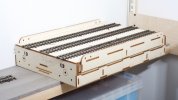
    The intention is to build a fairly adaptable and reconfigurable fiddle yard which I can re-use later when I build a more sophisticated layout. Also, the 1200 mm module easily fits in the back of a Mk2 Yaris with the rear seat folded and plenty of passenger legroom. So if Heybridge Basin turns out to be any good, I can take it to shows.

    I have done all of the "structural woodwork" for the baseboard modules so I can relax with this done and maybe I will have a go at the wagon this week.
     
    Last edited:
    Gloucester 4-plank wagon (1870s)
  • Richard Gawler

    Western Thunderer
    Of course!

    View attachment 187671
    Coming next - a ballast wagon from Gloucester.

    Three weeks later than intended, I am building a dumb-buffered wagon from a white metal kit by Jim McGeown, the proprietor of Connoisseur Models. This is an old kit from some years ago, which Jim has asked me to have a go at building. I have a feeling the kit might reappear in Jim’s catalogue if people ask him for it.

    DSC_3195.jpeg
    1/ The kit includes the parts to let you build the wagon with an early-style brake acting on one wheel, or a more modern brake acting on two wheels on the same side. I am building the earlier version so the model can look suitably at home as a ballast wagon on my late Victorian railway.

    First impressions are extremely good; this kit (like others from Jim) seems to have been designed to let the purchaser actually build a model without having to re-work or renew key parts. For someone whose first attempt at a white metal kit was a Will’s GWR U1 tank (4mm) around 1980 and hasn’t done many such kits since, the castings are a revelation.

    This is my first attempt at assembling a white metal “railway” kit (as opposed to a static “scenic” kit) using solder. All of my previous attempts at loco bodies and wagons have used epoxy glue, so please bear with me if there is more detail here than we really need.

    DSC_3339.jpeg
    2/ There were some pinholes in the tops of the long sides, which I filled with 100-degree solder. I am doing the whole build with this solder unless I say otherwise.

    DSC_3343.jpeg
    3/ The flash around the W irons (photo 1) was really thin and came away with a knife and by prodding with a cocktail stick. After I cut off the supports for the modern brake gear, I found small holes in the solebars and these holes proceeded to open up when I tried to fill them with solder. Discretion took over here and I filled them later with Milliput.

    DSC_3350.jpeg
    4/ I tacked the sides onto the solebars and then soldered the joints solid. Then I put in the first three wheel bearings . . . the holes in the axleboxes need to be opened up but the castings come with a rebate (photo 3) to hold the flanges of the bearings.

    DSC_3352.jpeg
    5/ I have drilled out one of the axleboxes oversize (3 mm instead of 2.5 mm), the idea is to use this bearing to set the two axles parallel with each other.

    There are eight cylindrical holes on the insides of each solebar. I guess these reduce stresses during cooling so the castings come out of the mould nice and straight. I filled all of these holes with Milliput. Any filler which uses water as a lubricant and can set underwater too has got to be good, although sadly this one doesn’t stick to brass very well. I used Milliput to fill the holes I found at step 3 as well.

    DSC_3358.jpeg
    6/ I am assembling the model around its brass floor panel and I have soldered the first side to the bottom of the floor as well as to the top.

    I put these efforts into the ultrasonic bath to complete the day. I dipped my fingers into the water too and discovered the machine cleans out the dirt under finger nails pretty well. I have also just realised none of the photos show the outsides of the wagon but they are looking good and will appear in the next installment :)
     
    Last edited:
    Wagons for the railway - internal, private owner and foreign
  • Richard Gawler

    Western Thunderer
    DSC_3466.jpeg
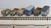
    The Heybridge and Langford Light Railway now has all of its own wagons:
    • the tender truck serves as a combined loco coal wagon and shunter's truck (it looks best coupled to Nellie the crane tank)
    • next are two opens, one for PW equipment and other internal operations and one for ballast
    • there is a van and an RCH open (Dapol), both for commercial traffic within the limits of the railway
    • the ex-Mid Wales Railway break van would have been replaced by something more modern around 1906
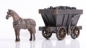
    There is also the chaldron wagon (more loco coal), which I see as a scenic feature, perhaps with a horse.

    I think a nice thing about this collection is that I have kits from white metal, brass, plastic and MDF, and only one RTR; and there isn't likely to be another railway out there quite the same as this one.

    One day I can have a go at repainting the various "bare wood" interiors.
     
    Last edited:
    Charlie - painted
  • Richard Gawler

    Western Thunderer
    After all of the problems I had with the stationary boiler from Duncan Models I have assembled a horse from the same source.

    View attachment 185963
    This is two whitemetal castings plus detail parts, and the parts fitted together with only a little filler. There was hardly any cleaning up to do either, much better.

    Painting is another matter for me, this is going to get subcontracted out.
    'Charlie' returned from Dan Evason (Tunnel Lane) yesterday and, well, I think his work here is fabulous.

    DSC_3500.jpeg
    My brief was, "he could be a brown or a grey, whichever you like". Definitely worth sharing, I wouldn't post my own painting efforts at this level of enlargement.

    DSC_3491.jpeg
    I intended Charlie to pair up with a Phaeton, but I think he looks good with the chaldron wagon. The setting (when I build it) is, after all, primarily a model railway layout.

    Charlie wears a harness for a light horse. From looking at old drawings, I believe this is fine for moving the chaldron or a small cart. Charlie had a namesake who was the last working horse on BR, a larger horse with a heavier harness tasked with moving much bigger and heavier rolling stock.
     
    ( Diversion : GER Y14 returns to Ambergate as a complete loco )
  • Richard Gawler

    Western Thunderer
    Trial runs on a stud-contact garden railway

    View attachment 175492
    A trial run of the Y14 chassis plus tender on the railway belonging to a club member was very promising, with the chassis hauling its "power pack" plus their 16-wagon train with ease and needing only the 4 oz weight to provide enough adhesion. So it looks like the body (not started yet, probably 250 grams) will give the chassis enough adhesion to haul a decent train without adding much if any additional weight.

    View attachment 175491
    Some of the trackwork dates back to the 1960s. The owner build the pointwork without plans or standards, and the crossing flangeways are a little more generous than Peco Setrack ones. So the Slater's FS wheels gave a pronounced wheel drop, but they stayed on the track.

    View attachment 175490
    The only problem was derailments caused by holly seeds, of which there were a few dozen to pick up.

    The garden is large by modern standards . . . I carried the r/c transmitter about 18 m (say 60 feet) away from the loco and control remained robust. This distance is further than I can imagine wanting to go to control a model train.

    So really, a fine trip out.

    A visit to the Midland Railway.

    View attachment 181716

    I took the loco to a friend’s railway earlier today. We began with this 16-wagon coal train.

    View attachment 181717
    The track here is coarse standard and electrified using stud contacts. The loco ran really well everywhere it could cope with the track. It floundered on some of the pointwork with tighter curves (5 feet and less), and where the toll of winter has left a couple of broken fishplates.

    View attachment 181718
    Then we tried a 30-wagon train. The loco could get this underway and keep it moving on the main line, but ran out of traction adhesion trying to pull the train through a facing crossover. This seemed like being right on the threshold of exceeding expectations. I added 110 grams of weight to the loco and it did exceed them. (The train is on the 'wrong line' here because it is too long for the train turntable behind it, and it will shortly cross to the correct running line.)

    View attachment 181719
    This is a freight loco so I will have to imagine this is a working of some empty coaching stock during some kind of trial or locomotive exchange with the Midland.

    Only four photos but all in all this was a wonderful time. The loco works, and works well. The major unknown now is how long it can run on a charge of its batteries. I suspect this will vary so much according to speeds and loadings I will never really know.

    I left my Y14 untouched for a full month. I was convinced I could hear something binding in the chassis (my ply baseboards do rather amplify this sort of thing) but a mate said the running seemed perfect to him.

    Received wisdom was to give the loco a run before trying to improve anything, and the opportunity to do this arrived yesterday.

    P1050232.jpeg
    So, back to the Midland Railway at 'Ambergate'.

    P1050244.jpeg
    This double junction has its origins in the 1960s. The builder did not know the standards for trackwork at the time, and so they devised their own. I suppose, the work is a little tighter than today's GOG 'coarse standard'.

    P1050236.jpeg
    All of the running was tender-first because the tender weighs as much as three wagons and I thought this was a suitably demanding scenario.

    P1050237.jpeg
    The model performed faultlessly and never derailed during I suppose a total of ten out-and-back round trips.

    P1050242.jpeg
    The regional discrepancies seemed to be accepted by all.

    The loco really does need a crew. I have painted two sets but they are dressed for the 1950s and I want something for the late 1890s - I still need to find out what this is. Although anything would have looked better here.

    This was a NEEGOG club meeting and really was a grand day out. Several people commented on how well the loco ran so I must reassess my own standards of what is adequate. The loco ran at least 300 metres in all and never derailed so it might be best to leave the chassis alone and continue the running-in another day. I wonder how long this should take?
     
    Last edited:
    GER 10 ton van (1910)
  • Richard Gawler

    Western Thunderer
    I want to return to the model making here while I build another wagon. I have at least three completely disparate sets of ideas for future projects – the headgear on the crew, the swans in the basin, and the private coach, but none of them have quite ‘gelled’ to make me want to start on them. And this isn’t counting the list of locos I want to build, and indeed the whole “Heybridge Basin” diorama. I can mull them over in my mind while I build the 10-ton GER van from Jim McGeown.

    DSC_3527.jpeg
    The contents of the kit. You get a second identical etch for the second side and end and so on, and I am sure I had all six coupling links too.

    DSC_3528 (1).jpeg
    Rivet impressions formed using my automatic centre punch. The tip of this fits into the half-etched recesses perfectly, so they come out in straight lines and all the same depth. I find this hugely easier, neater and quicker than using my rivet press. I thought this was brilliant idea of mine until I did a quick search online and realised other people discovered this years ago. The working surface is the usual green cutting mat.

    DSC_3544.jpeg
    It is easy enough to form the first fold in the solebars. For the second fold, I take the metal about a third of the way round before the jaws get in the way, and then tease the solebar into shape between the jaws. I think the trick here is to weaken the fold lines before starting, I run a scriber along the lines several times. The masking tape protects the rivets from the jaws of the vice, this idea is from Jim’s instructions for the kit.

    DSC_3552.jpeg
    On the inside of the sides, it is worth reinforcing the folds with sections of solder not a continuous fillet. This stops the solder running out through the holes and onto the outside of the model. This is my second side.

    DSC_3547.jpeg
    I soldered up the corners from the inside. The capillary action draws the solder into the joint (fair enough) so the trick is to control things so almost nothing appears on the outside. Needless to say this is my fourth corner.
     
    Last edited:
    Four-wheel saloon part 3
  • Richard Gawler

    Western Thunderer
    Final details before painting.

    View attachment 184784
    The door handles, buffers, coupling hook and vacuum pipes are all from the kit.

    I used the lathe to bore the holes in the buffer stocks, and to dress the buffer heads. I tried to double up the door handles to make them look a bit more robust but I dropped the first pair onto the carpet. Even with only four doors to equip I could see I was going to run out of handles so these are single thickness parts from the kit.

    View attachment 184783
    The buffer heads are resting loose here for the photograph. The castings for the axleboxes and springs are neat and well-made but I will leave these off for now. So I can remove the wheels and their axles during painting.

    View attachment 184785
    'Blackwater' doesn't have a train brake and the van is unfitted too, but I can see the sort of look I want for my railway in here.

    Back to the four-wheel coach, I have had a rethink on leaving off the axleguards. The idea was to make painting easier but really it will make painting harder because fixing them later with solder will ruin the paint and any attempt with glue has a fair to good chance of making a mess. So I have soldered the axleguards into place.

    DSC_3886 (2).jpeg

    DSC_3888 (2).jpeg
    Really this post is an excercise in photography rather than model making but I hope I can be excused because I want to build another coach (a brake composite) before painting this one. Also I am very pleased with this model. The buffer heads are loose for the photographs.

    The background here is glossy white paper which was the cover of a A2 size pad of paper. The surface is covered in tiny marks from taking photos but they don't show up.
     
    Last edited:
    Four-wheel brake coach (1870s on)
  • Richard Gawler

    Western Thunderer
    I have succumbed to a Dapol Stroudley coach. The layout will be a whole lot easier to operate if I have a brake coach, this will let me keep the break van for freight trains. The private brake composite won’t really be suitable for this (and I don’t feel ready to build this yet) and I want a second coach to help me to visualise the look of the diorama of Heybridge Basin. And there were only two left in stock at Hattons, so it was pretty much now or never.

    This model is really a factory-built and pre-painted kit, and one where the assembly work has used minimal amounts of solvent and glue I guess for speed and efficiency. So dismantling is easy, sometimes a bit too easy but if bits fall off now I have a chance of fixing them back better . . .

    DSC_3907.jpeg
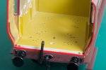
    The guard’s compartment is rather visible (through the windows!!) and the floor moulding is covered in holes to let it this part build into different models.

    DSC_3926.jpeg
    I have covered the floor with some 1:48 scale dolls house flooring paper. Years ago I assembled an engineering log book using a very thin double-sided sticky tape to hold lots of paper notes and sketches. This book is still as good as when I made it so I have used this sort of tape to hold the flooring paper. The brake wheel and its column are castings left over from the Y14.

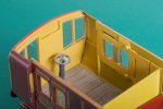
    The inside end of this compartment arrived bright red like the outside. I have repainted this using Vallejo ‘Yellow Ochre’. This is a remarkably good match for the factory colour on other inside parts, it is not perfect but I cannot tell the difference looking in through the windows. The coverage over grey primer is very good for a yellow.

    DSC_3931.jpeg
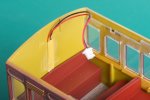
    I bought the version of the coach with a light bar and DCC lighting. I have put a strip of styrene over the lighting wires running up the other end of the body, again not perfect but it looks better.

    The success in the guards compartment encouraged me to paint the borders of the glazing mouldings to match. I think this takes away the worst of the “one-piece moulded look” on the inside. The design of this model is clever, it uses the same glazing moulding for both sides.

    DSC_3936.jpeg
    There are two oil lamps for the three passenger compartments. One is located directly above the backs of two seats, but the other was offset by about 4 mm. I don’t know if this is correct for the prototype but somehow it looked wrong so I have moved it. This sort of operation is one where the low coverage of the factory solvent helps a lot, the details pry off with a scalpel.

    DSC_3932.jpeg
    I took out the decoder and put in a blanking plug and the lighting effect is still the same when running on analogue DC. The lights come on at a low controller setting and stay on at the same brightness.

    DSC_3946.jpeg
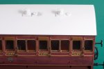
    I realise this still looks very much like it did out of the box, but it did all go back together :)

    I want to completely rework the lighting so there are three LEDs in line with the three oil lamps and not four LEDs spread along the coach. If anyone knows the circuit for a constant-brightness lighting circuit please do say. Maybe I could extend the circuit into the saloon and keep the two coaches coupled together. The inner end of the Dapol coach even has a close coupling cam under the floor.
     
    Last edited:
    . . discussion of coach lighting
  • Richard Gawler

    Western Thunderer
    Richard, train tech now gauge master do a motion switch system which i'm sure a man of your caliber could adapt;)
    I had one of these in a 4mm scale coach now sold. They are good if you want a general spread of light or a representation of modern lighting units.

    I think, if I want to represent oil lamps then I will be paddling my own canoe, but maybe I can exploit the electrical pickups on the Dapol coach to charge a small battery to keep these glowing at a suitable brightness. They will end up much brighter than real oil lamps if they are going to make a noticeable effect on the interior.
     
    Top