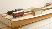
7mm Heybridge Basin

Scenic development for localisation New
  • Richard Gawler

    Western Thunderer
    View attachment 188062
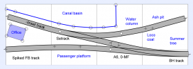
    George @Herb Garden : The track plan is very is close to this, but I am showing a Peco curved point here in AnyRail to represent a mildly-curved A6 which I am using.

    @adrian : The baseboard is from a standard G&H module. I placed the track on the board as carefully as I could and marked a line to show the rail nearest to the basin. Then I marked another line parallel to this and cut out the baseboard top to suit - see Dockside tracks. It was then easy to lay the cross members onto the top to mark them for cutting out. The construction sequence for the big bits was (with the structure upside down) top, three cross members, both ends, front and rear, basin base; and then trimmings like the back of the basin and the three diagonal braces.

    @Yorkshire Dave : The operating practice on the Navigation was for sea-worthy vessels to tie alongside near Osea Island, where their loads were transferred to old Thames barges. These were towed across to the sea lock, moved into the basin, and everything was moved again this time onto barges. There is more in part 1 of my back story, this part of the story is factual. I will be very happy to make some passable looking water. Some kind of watercraft would be a bonus but it isn't a must have. Shoving all of this track into five square feet is probably a cliche in its own right, but if I can end up with a better test track and some experience of larger-scale scenics this will be good.

    I have been pondering the scenic development of "Heybridge Basin". The track plan has been fixed since early June but some thought is needed to show this is "Essex" and not "in England". So, thinking about localisation, the ideas so far are the following:

    Great Britain
    • Sleepers 9 ft long, set at the usual British spacing with spiked FB rail
    • Facing point lock on the passenger line
    • Architecture item 1: platform shelter
    • Navigation to look like a canal not a river
    • Wildlife: mute swans in the basin
    East Anglia
    • Water column of GER pattern
    • Large sky on the backscene
    Essex
    • Ballast: local sand and gravel (independent railway, so not GER ash from Stratford)
    Chelmer and Blackwater Navigation
    • Architecture 2: small office building from Paper Mill Lock, this is seven miles away on the Navigation
    Heybridge Basin
    • Waterfront defined by stone slabs on brick walls, like the sides of the sea lock
    • Early use of concrete for building blocks, pioneered by E H Bentall
    • Station name board “Heybridge Basin” (!)
    I would love to add "painting of local buildings on backscene" to this list, but while the usual constraints of time and money always apply, there is is also the matter of ability :))

    Screenshot 2023-09-09 09.22.12.png
    I have built, it seems, seventeen model railway layouts. Only four worked out really well, and these were the four where I planned the treatment of every square inch before I even laid the track. It makes sense really, especially if some more of the baseboard top has to be cut away. There is no rush, but I do think "Essex" deserves more than "ballast". This is the 1890s but I still await the first TOWIE remarks :cool:
     
    Tracklaying
  • Richard Gawler

    Western Thunderer
    The first turnout is now glued down forever . . .

    DSC_0674 (1).jpg
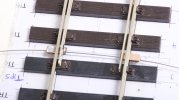
    Unfortuately, the tiebar using piano wire and two offcuts of copper clad (September 2022), which I thought was really neat, broke before the turnout reached a baseboard. So I am having a first attempt at an under-baseboard tiebar.

    DSC_6227.jpeg
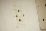
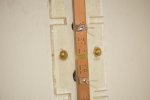
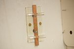
    The new tiebar assembly is from C&L. I have glued its acrylic base onto the baseboard with Evo-Stik contact adhesive.

    DSC_6231.jpeg
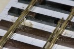
    The tiebar assembly uses two vertical lengths of 0.5 mm piano wire to move the point blades. So there is space to model a scale tiebar.

    DSC_6228.jpeg
    I had a go at arranging these wires to pivot on the tiebar to reduce torsional stresses but this merely increased their lateral movement and the associated stresses at the blades, and I ended up with too much slop.

    DSC_6234.jpeg
    So they are now soldered solid. This assembly "seems to work" but I have doubts about the longevity of the link wires. The blades are code 124, but on the bright side they are planed along most of their lengths and they are longer than a similar geometry in 4 mm scale.

    DSC_6240.jpeg
    If the tiebar had been an inch longer I could put a stall motor or a switch mechanism directly beside it. I will have to extend the tiebar or arrange some kind of linkage.
     
    Last edited:
    Wiring and Point Control
  • Richard Gawler

    Western Thunderer
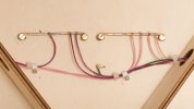
    If I am sensible, I can keep the external wiring into the layout down to two wires. I have wired the track as if for DCC and for me this will support one analogue loco and a high frequency lighting unit. If a second loco enters the stage, this will be using radio control. The lighting unit can run a couple of gas lamps as well as coach lighting.

    DSC_6365.jpeg
    My busbars are copper wire on brass wood screws, and the colour coding is using up the colours I rarely use. The cable clips are ones for 3 to 5 mm round cable, fixed underneath the baseboard with screws in place of the masonry nails.

    DSC_6339.jpeg
    I turned the layout as needed to let gravity hold the wires, this makes looming a lot easier and neater.

    I rather like the droppers off the blades idea. It gives a decent length for them to flex, so I don't think I'd worry about torsion.

    A short length of brass wire with a loop at one end for the Tortoise spring wire, and soldered at the other to your tie bar should do the trick.

    DSC_6371.jpeg
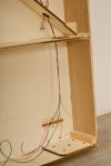
    I have extended the under-baseboard tiebar as suggested by Simon.

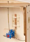
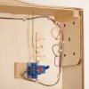
    DSC_6367.jpeg
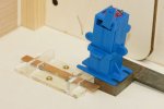
    The block of plywood is here to make sure I get enough throw from the point mechanism. I cut the block oversize to give me more area for the glue holding it under the baseboard.

    This is a “Blue Point” mechanism of North American origin. It gives me a latching mechanism and a changeover switch, but the action above the baseboard is as clunky as a solenoid :headbang:

    The mechanism supports a second push rod, so I could arrange control from the front of the layout one day if this is useful.

    The push rod is, of course, a bicycle spoke. The nipple can get a locknut when I find a suitably primordial-spec fixing. Probably a "2-56".

    But at last, I can play trains :)
     
    Last edited:
    Operations
  • Richard Gawler

    Western Thunderer
    Hmmm! I had a rocking lever like this on an N gauge layout where I was determined to persuade one H&M point motor to work two points. Eventually I got it to work, but after the layout was stored for a while it didn’t!

    DSC_6393.jpeg
    In broad terms, I see operations a bit like this:
    • For freight, a loco will haul a wagon from the fiddle yard (right) into the headshunt and then propel it into the kickback siding. When a loco passes over the Setrack point, it “kicks” the blades into place if they are set incorrectly. (Though most likely they will be correct following the last exit of a train from the headhunt).
    • For passenger, a loco hauls its coach into the passenger platform. The task of getting the loco onto the other end of the train for its departure will involve setting back and then the use the headshunt and a rope. The route of the Setrack point stays unchanged throughout this.
    If this all works out okay, I’ll stay with it. If I really want single-lever control of the points, I might look at a bowden cable from the actuating arm of the Blue Point around to the Setrack point. Or of course a rocking lever. This might be easier in 0 gauge than N gauge because it will be longer and will rotate further.
     
    Last edited:
    Extension Section for Sea Lock
  • Richard Gawler

    Western Thunderer
    I saved some offcuts of the iron-on veneers to use them on the extension for the sea lock. These veneers have a short storage life, perhaps three or four weeks. I wrapped the offcuts in cling flim and put them in the garden shed away from the central heating but they still curled up along their long axes. So when the kit to build the extension baseboard arrived, I built it straight away.

    DSC_6398.jpeg
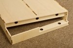
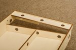
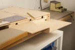
    The baseboard is a standard module from Grainge and Hodder, 400 mm long and 400 mm deep, with the front cut away to make a space for the sea lock.

    DSC_6401.jpeg
    I have reinforced the front edge of the top and the slimmed-down front of the module with parts provided to use as diagonals.

    DSC_6408.jpeg
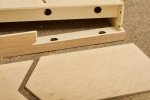
    The structural bases for the sea lock (right) and the extension of the basin (left) are some 6 mm ply left over from another project. I cut locating slots in the frame not the new parts because this makes it so much easier to align the new parts.

    DSC_6410.jpeg
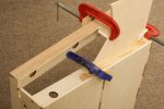
    Fixing the extension of the basin. The block of softwood here is simply holding the base of the basin level, it is not a part of the model.

    DSC_6420.jpeg
    The idea is to make the course of the Navigation appear to curve to the right and drop away towards sea level.

    The original idea was to put the lock gates at the baseboard joint, but this wouldn't work because the arm for working the gate of the sea lock would be crossing the headshunt. So this arm will be beyond the headshunt, near the pencil.

    The veneers flattened themselves out quite well after I brought them back indoors, but they don't like being stored for any extended period.
     
    Top