Hartley Hills, LNWR c1900 - buffer stops, how do you build yours?

Dog Star

Western Thunderer
Several months back John and I spent a few productive hours in trying to establish how we would ballast the trackwork and with what materials. How to do the task was fairly easy to decide and the method is described below.

Choosing the colour and texture has been a difficult and long drawn out affair as neither John nor I were around at the turn of the 19th century... and contemporary photos could provide an insight into texture without a lot of help as regards colour. Adrian (Buckjumper) has described some of the reasons why the B/W photos of circa 1900 ought not to be relied upon for indications of colour.

The written word has noted "old" ballast as being ash and slag, with a covering of congealed oil, coal and cinders; this description has driven our search through the Woodland Scenics range and we had almost settled upon a mix of fine cinders, medium cinders, a smattering of fine dark brown and a light dressing of fine soil. And then a member of the Basingstoke MRS offered a different route forward... with a bag of "grog" or spent foundry sand from a cast iron foundry in Witney. The colour and the texture are the closest to the pictures and description so far... sold!

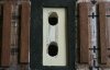
John visited yesterday and we decided to ballast a scetion of the Up Goods line... and here is the result:-

hh-slag-ballast.jpg


The spent sand was spread over the track and tamped into place with paintbrushes of different sizes and the flat of a 6" ruler. A mist of water / IPA / fairy was sprayed over the ballast to wet the material... leaving the ballast for a couple of minutes to ensure that the mist spray had gone to the bottom of the bed - a further misting being deemed necessary where the ballast was not uniformly wet. Woodlands Scenic Cement was applied with a bulb pipette carefully so as to not disturb the ballast... a second application of the glue was made some hours later to ensure adequate binding - use too much glue too early and the result is like e slag heap on the move.

Woodlands Scenic Cement is used in preference to PVA because the product dries clear and matt... and retains a springiness.

The result is not quite there yet, needs to be a tad darker and possibly with a binder to help with the desired impression of ash / slag that has been down for yonks. Plenty of scope for dry-brushing.

The next step in fettling of the track work is to decide on materials for the Up Main.

regards, Graham
 

Tony West

Western Thunderer
Hi Graham I had a good time yesterday and it was good to see some ballast down and glad you liked the wagons
Ta
John !!...you surely didnt think you could drop a mention of wagons into the message without photographic evidence ???!!!:D
Cheers Tony.
 
S

Simon Dunkley

Guest
And then a member of the Basingstoke MRS offered a different route forward... with a bag of "grog" or spent foundry sand from a cast iron foundry in Witney.
I am trying to remember where I saw this idea, possibly Llanastr. Strikes me that if one of the outfits that sells tubs of granite, etc, at shows were to pick up on this and approach their local foundry, it would be a win-win-win scenario: foundry gets rid of sand, trader has an extra income stream, and the rest of us can buy it in the amounts we need.
 

Dog Star

Western Thunderer
... Strikes me that if one of the outfits that sells tubs of granite, etc, at shows were to pick up on this and approach their local foundry, it would be a win-win-win scenario: foundry gets rid of sand, trader has an extra income stream, and the rest of us can buy it in the amounts we need.
The material is available from a member of the Basingstoke Club at £1 per bag of 250-300 gms dry weight. I could not work out how many bags we would need for Hartley Hill... so a 25Kg bag arrived last week, that should do it! :eek: :rolleyes: :cool:.

regards, Graham
 

Dog Star

Western Thunderer
The sand does look very good in the yard it looks a different colour in daylight than it does in the photo
The difference may be due to two things:-
1/ the glue has dried out and lightened the colour slightly;
2/ the photo was taken with illumination from a daylight lamp.
 

Tony West

Western Thunderer
Graham ,
I very much like the results acheived so far as ballast can be a very hard item to model realistically. Many moons ago I started construction of Rugby Central in 4mm. When it came to ballasting the yard and headshunt I decided that the real mc coy was the best thing to use , so I collected an old ice cream tube full of the stuff from just behind where the signalbox once stood....dried it out in the oven ( when SWMBO had gone shopping !!) and proceeded to crush it down to an acceptible size.
All seemed to be going well until I applied the dilute pva.....it turned it jet black...stood out like the proverbial!.So much for using the real thing .
Cheers Tony.
 

Dog Star

Western Thunderer
All seemed to be going well until I applied the dilute pva.....it turned it jet black...stood out like the proverbial!.So much for using the real thing...

Not much help after the event... I have spent many hours experimenting with materials to ensure a repeatable method of ballasting track for an acceptable appearance. First revelation was that "PVA" was not the great panacea in that the glue had tendency to colour whatever I used for the "ballast" - Woodland Scenics "Scenic Cement" has no visual impact upon whatever I have used for scenic textures (ballast, grass, cinder paths). Second realisation is that the weight of "real stone" is so much more than other "nut / shell" based stuff.

If Woodland Scenics had something in the range which is suitable for ash/slag ballast on a goods line then I would have used that... grog is an acceptable material without the weight of granite chips.

regards, Graham
 

Dog Star

Western Thunderer
A fine day last Sunday and I wandered down the High Street of Hartley Hill on my way to the station, pausing to contemplate the victuals in the local Co-operative and then the latest in Plus-6s available from the Emporium. The local PW Inspector had sent a boy to let me know about an occupation of the Up Fast for relaying. Last month a Precusor tank had drawn out of the Down local platform, with a returning service to New Street, and come a cropper on the trailing lead from the diamond to the Up Fast. Hell has no fury like a Station Master who can see the Monday service in tatters even before the first commuter train has arrived.

Monument Lane cleared up the mess and were more than happy to drag the engine back to Stafford for attention - double time on Sunday was most welcome. As soon as the engine was clear of the scene the PW gang was able to get to work on the repairs. Whilst the engine had suffered little, just twisted guard irons and flange marks to the bogie wheels, the same could not be said for the track. To help WT-ers understand what was what here is the station layout:-

Hartley-Hills-web.jpg
Thankfully - actually the Head Ganger used Olde English - the Precursor tank had passed over the diamond and the common crossing of the trailing lead from the Down local platform. Not so good for the switches of turnout 3A and the common crossing of turnout 4A, both had suffered from cracked chairs and / or twisted rails. The Head Ganger had made a preliminary check on the Switch and Crossing fittings when he arrived on the scene and had telegraphed a list of parts to the local PW depot... those items arrived not long after the engine had been towed away and the carriages moved to the carriage siding for attention from a Carriage and Wagon Inspector. The PW gang had worked late into the night to replace the common crossing of turnout 4A and the stock rails, switch rails plus slide chairs of turnout 3A... using standard parts which left a problem in that the toe of turnout 3A was about three sleepers beyond the end of the crossing legs of turnout 4A. Not to be stumped by such a concern the gang had cut and fitted a short length of rail to bridge the gap between turnouts 3A and 4A... and then slapped a temporary speed restriction, of 5mph, on the Up fast through the station and past turnout 4A. In case the significance of this imposition is lost in the mists of time, the Up Fast is part of the West Coast Main Line and carries all of the LNWR traffic from Manchester to Birmingham.

And so to the reason for the occupation on this particular Sunday - the PW gang is going to remove the short length of rail (no more than seven or eight feet in length). To achieve this task the gang has to either replace the vee of turnout 4A with a similar item which has a longer point rail... or replace the adjacent stock rail of turnout 3A with a longer item. Whichever course is taken the result is that the short rail is removed and the temporary speed restriction is lifted.

So, in the best spirit of WT, time for the competition. On the basis of there being only two options for removal of the short rail, which option would you choose and why?

regards, Graham
 

S-Club-7

Western Thunderer
Is the stock rail machined in any way to seat the switch blade?

If not, then I'd replace the stock rail with a longer one. Why? The vee rails are likely to require more frequent replacement due to wear and damage at the crossing. Being able to use a standard vee straight from the stores would be of benefit in situations such as that described above. The stock rail, unless it's machined, can just be cut to length, drilled and joggled on site.

Actually, if the replacement stock rail is too long to be made out of a standard length of rail then you'd have to replace the very short filler and the current stock rail with two medium length pieces. And then adjust the sleeper spacing around the new joint.
 

John D

Western Thunderer
I am trying to remember where I saw this idea, possibly Llanastr. Strikes me that if one of the outfits that sells tubs of granite, etc, at shows were to pick up on this and approach their local foundry,

I used foundry sand on Alexandra Yard in the late 90's ,a supply being obtained from a local industrial outlet, now long gone. I does look the biz as the particles vary from dust to fine and would ,as said, best be put down using the Woodland Scenics 'glue' . At the time I used PVA which worked OK but you had to be careful when dry as,being sand like, if you caught you hand on it it was good at skin removal:(. I oversprayed it to get rid of the jet black colour getting something more appropriate.
Anyone tried the ash ballast from C & L ?
 

Dog Star

Western Thunderer
A post to the Permanent Way forum, here , covers the manufacture of switch rails, those switches are for Hartley Hill as part of turnout 3A. For this layout the turnouts are to be operated by motors under the baseboard so some method of transfering the drive from "under" to "above" is required. My current preference is Fulgurex motors driving the switches by way of a sliding action... which necessitates slots in the baseboard surface, as here:-

switch drive 1.jpg

Sufficient underlay foam is removed to allow cutting of the slots plus a little more so that when the foam is replaced then the cross-track joints are under the timbers. This is a photograph of the trap point to the carriage siding (no.2), 14" timbering to the left of the image and 10" sleepers to the right.

After cutting the slots the underlay and timebrs are replaced, then two slits are made in the foam to correspond with the slots in the baseboard surface. In this photo there is a piece of stripwood to show the location of the slit.

switch-drive-2.jpg

The next two images are of the facing turnout in the Up Local platform loop (no. 4B) and show the switch in the closed and open positions... that is, to show how the drive rod can move through the slit in the foam underlay. As with the trap, this turnout is done with 14" timbering throughout to represent LNWR PW practice pre-1900.

switch-drive-3.jpg

switch-drive-4.jpg
 

Attachments

  • switch drive 1.jpg
    switch drive 1.jpg
    1.9 MB · Views: 4

Dikitriki

Flying Squad
Hi Graham

That's a really neat way of operating the turnouts - well hidden - but what's the mechanism below the baseboard?

What really took my eye, however, was the accuracy in your filing of the blades in the top photo:thumbs: Excellent!

Regards

Richard
 

ZiderHead

Western Thunderer
Thats what I was thinking - when you see it in place it really shows the worth of all that work on the switch blades, bet the running is excellent too :thumbs:
 

Dog Star

Western Thunderer
This is an unusual post for me in that the content is about no progress... or rather a tale of how twelve months went by whilst I wondered and pondered on what was wrong with the manner in which I had set out the timbering and stock / switch / closure rails for a turnout of Hartley Hill (the trailing lead from the Down Local platform road across to the Up Main... shown as turnout 3A in the station plan for Hartley Hill). In essence there seemed to be a conflict between various sources of PW information such that I could not work out where the switch rail and stock rail joints were placed in one particular turnout.

For those who have a long memory, or maybe a good reference library, Modellers Backtrack Volume 4 of 1993-4 has a series of permanent way articles by Keith Horne. In those articles the author developed a timeline for the design of switches and crossings - this thesis is a good read and provides an understanding of how railways moved from the dark ages to the emergence of standardised Switch and Crossing practices (post grouping adoption of REA principles). I am happy to acknowledge the significant contribution that Keith Horne's writings have made to my understanding of LNWR turnout practice in the Edwardian age. In a similar vein, I want to acknowledge the help and advice which I have received from LNWR modellers who have each assisted in the resolution of the conflict without any suggestion that a GWR enthusiast ought not to question the history of LNWR practices; those who have helped include LNWR Modeller and Penlan of RMWeb... Dave Pennington who was the builder of a superb 4mm model of Stanmore... and some members of WT who expressed a desire to remain anonymous.


So this post provides a trail through the ups and downs of designing LNWR turnouts in the Edwardian period. If such is not of interest then pass this post by and move on to a later post which includes some photographs of the result of the struggle.

===========

Once upon a time, when Hartley Hill was just a sketch on a sheet of A4, discussions with John Lewsey were along the lines of "big curves, shallow crossings and long lead switches". As those discussions progressed a fellow member of the S7 Group was able to help by comitting the sketch to Templot - a task which needed some clarification of what was meant by “big curves, shallow crossings and long lead switches". Richard Carr produced a complete S7 template of the station throat using 60ft ruling radius for the down main, crossing angles of 1:8 wherever possible and a “C” switches. However, a C switch was not going to work with the trailing turnout from the Down Local platform to the Up Main where a D switch was needed as this turnout is curved with both roads of similar flexure... this simple statement was going to come back to haunt Albert (who featured in early posts on this thread, further tales of Albert’s abilities can be found in Keith Horne's articles).

Unfortunately C8 and D8 turnouts are not the stuff of LNWR late Edwardian S&C practice for such descriptions lay at least fifteen years in the future (generally a post-grouping concept). As the dateline for Hartley Hill moved back a decade, to the early years of the twentieth century, differences emerged between what was desirable for the turnouts and the templates which had been produced from Templot... for example, rail lengths of 30’ rather than 45’ (predictable), timber sizes (14" wide for LNWR, 12" in Templot), straight cut loose heel switches (LNWR) as against fully flexible semi-curved switches (Templot). Moving to a dateline of circa 1900 has lead to a long, drawn-out, battle to establish just what the LNWR PW Department was doing for S&C practice at that time.

The HMRS Journal has published, in volume 18, an article about the relationship between pre-grouping straight cut switch details and post-grouping flexible switches... so a 9' switch corresponds to an "A" switch, 12' switch to "B" switch etc. . This article details the length of switch blades, the length of switch planing and other matters relating to the geometry of a switch. The information in this article has been used successfully to develop LNWR turnout arrangements for the equivalent of the C8 turnouts on the original Templot templates. Not so with the D8 turnout - working out a straight cut switch equivalent of a D switch just did not lie comfortably with the geometry of the rails as shown on the templates. When I started on Hartley Hill I was given a copy of the LNWR PW Estimating Drawing for Turnouts in which was detailed the number of timbers in a turnout and the length of each timber. I had set out all of the turnout timbering using this drawing and experience was that the timbering diagrams worked with the 15' straight cut switch (equivalence of C switch). Unfortunately timbers set out in accordance with the drawing were not compatible with an 18' straight cut switch (equivalence of D switch as suggested by the HMRS article). The conclusion, a year ago, was that either I was not interpreting the timbering drawing correctly or that the LNWR switches did not follow the HMRS article. There the matter rested for some months whilst I contemplated where the problem lay in what I was trying to do.

About eighteen months back I had been given sight of various LNWR PW drawings for crossings and check-rails, those drawings suggested that a copy of a LNWR PW Handbook had survived, but where? Conversations with LNWR modellers at S4-Forum and Expo-EM led to an introduction to Dave Pennington who, in the last month, has provided a copy of another page of the Handbook - the arrangement of switches. This drawing showed that the LNWR was using 9' and 12' straight cut switches as indicated by the HMRS article... and that the other standard switch lengths were 16', 20' and 30' - not as implied by the HMRS article. and thereby was the answer to the niggle from the summer of 2012. Drafting a 20' straight cut switch onto the timbering set out for turnout 3A showed a pretty good match.

Apart from providing an explanation of why I could not get a 18’ straight cut switch (as suggested by the HMRS article) to fit the LNWR timbering arrangement the drawing from Dave Pennington revealed some other aspects of LNWR Edwardian S&C practice... such as:-

· The use of stud bolts to support the switch blade for the slide chairs on timbers 7 and 8 from the switch toe (REA equivalent likely to be block chairs);
· Block chairs on timbers 9 to 14 from the switch toe;
· Narrow plain chairs side by side on timbers 15, 16 and 17 from the switch toe;
· The length of planing for the switch rails (12’ 2.5” or 85mm in 7mm scale);
· The lengths of the switch and stock rails (“Side” rails in LNWR parlance).

So with this information I have been able to resume the construction of turnout 3A as is depicted in photographs in a subsequent post.

Regards, Graham
 

Dog Star

Western Thunderer
And here are the photographs of progress with turnout 3A of Hartley Hill - this can be thought of as the key part of the Station Throat, a curved turnout with similar flexure, a 1:8 crossing (to match the associated diamond) and 20'0" straight cut, loose-heel switches. If this turnout does not work smoothly / reliably then the reason-d'etre for the Down Local platform is for nothing (this platform is for terminating local services from Birmingham).

This photograph shows the timbering at the toe of turnout 3A. The coffee stirrers mark the positions of various aspects of the turnout design, reading from the right hand side:-
* toe of switch blade;
* end of slide chairs / start of block chairs;
* heel of switch rail;
* end of block chairs.
hh-3a-sw-1.jpg

As in previous photo and from above, the white spots by timbers 7 and 8 are the stud bolts on the stock rail.
hh-3a-sw-2.jpg

The stud bolts which support the switch rail between the first block chair and the end of the planing. I have not been able to decide if the LNWR stud bolts have a square end section or are circular throughout... if you know please step forward!
hh-3a-sw-3.jpg

hh-3a-sw-4.jpg

The toe of the turnout with the switch rail in position (temporarily). The planing of the switch rail is 85mm in length and extends over six slide chairs.hh-3a-sw-5.jpg

The switch from above.
hh-3a-sw-7.jpg

regards, Graham
 
Top