TFW’s workshop

Tim Watson

Western Thunderer
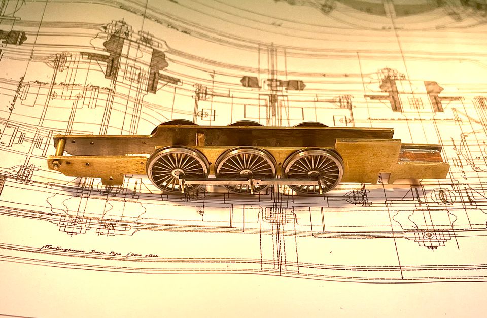
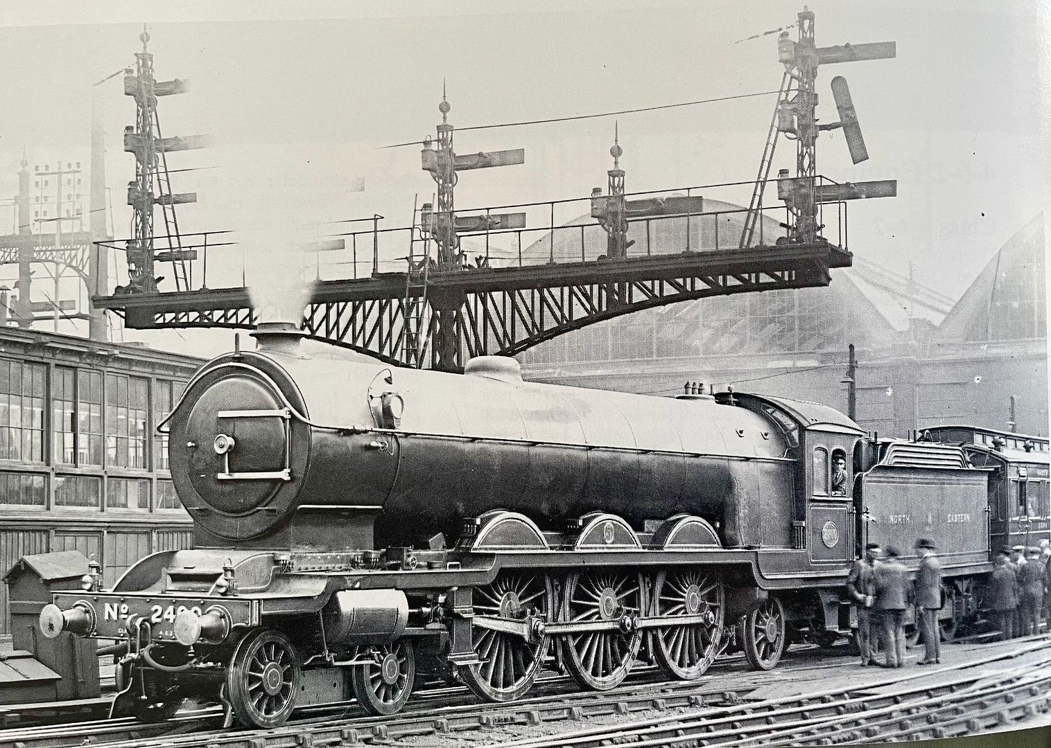
The next loco from the Darlington works in St Albans will be a Skittle Alley, AKA a Raven NER 4-6-2 No. 2400.
C8593C26-1072-4D47-87DF-08D31A36435F.jpeg

It will make a striking and exactly contemporaneous partner to Valour on CF. (Just needs someone to make a NER Dynamometer Car).

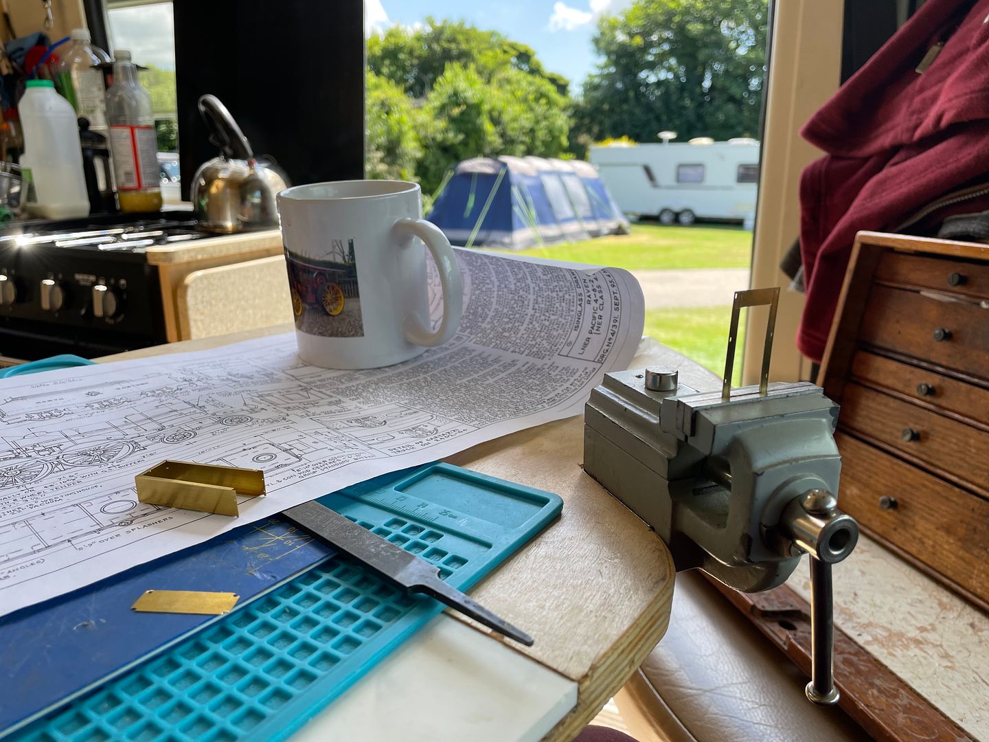
A holiday start was made on the tender, reduced from the original Steve Barnsfield artwork for Mick Simpson: many thanks to Mick and Chris Higgs for letting me have some etches.
C315E830-0EA6-4AA4-A9E5-B993A6EABFAD.jpeg


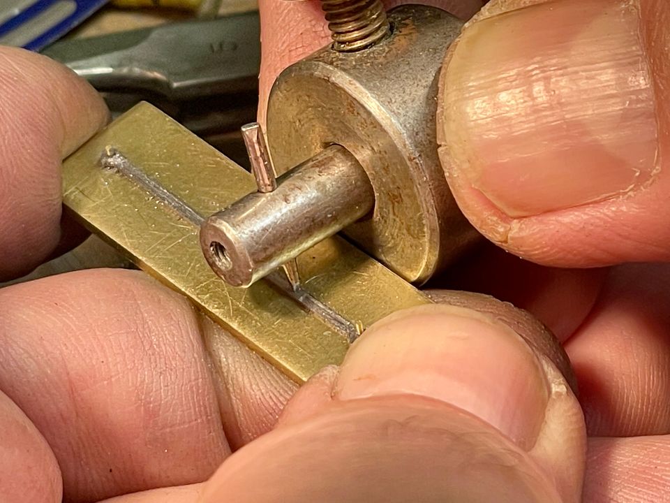
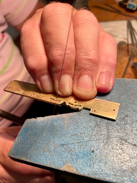
The fit of the parts is excellent and so the body work made good progress. The tank and bunker are made as two layers (I did re-do the sides as the first attempt wasn’t dead flat): the inner top flare section is half etched. This was swaged around a 1mm diameter rod held on top of the vice for the inner layer. The three smaller half-etched outer flares needed another method, however.
B735C0FF-766A-471C-9908-FEBA755F0D4B.jpeg

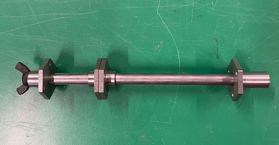
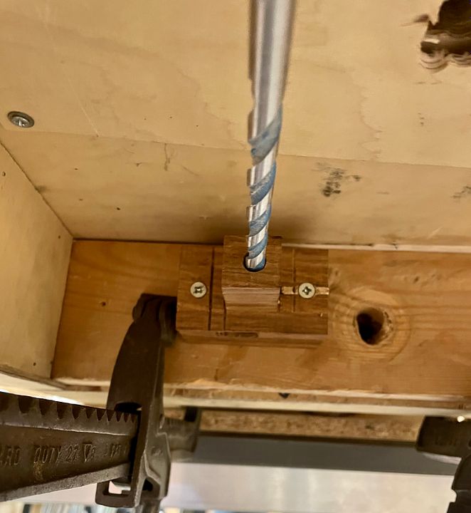
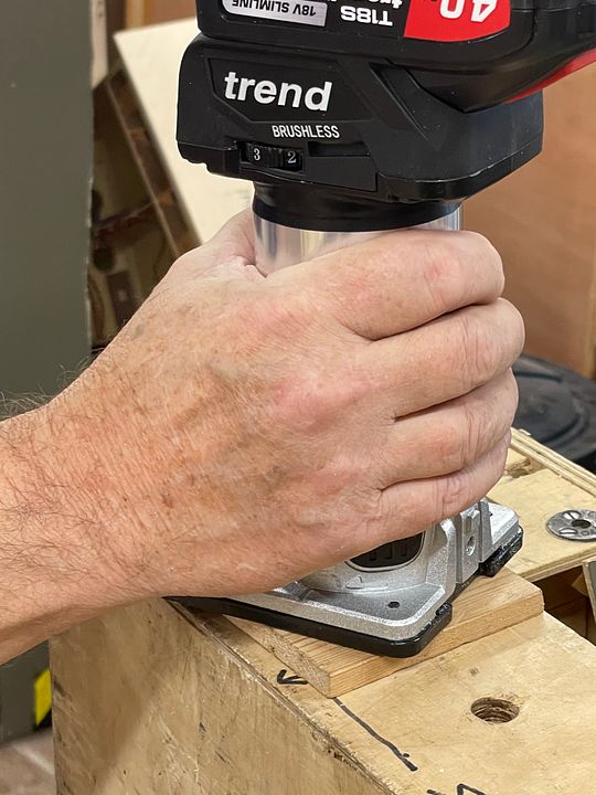
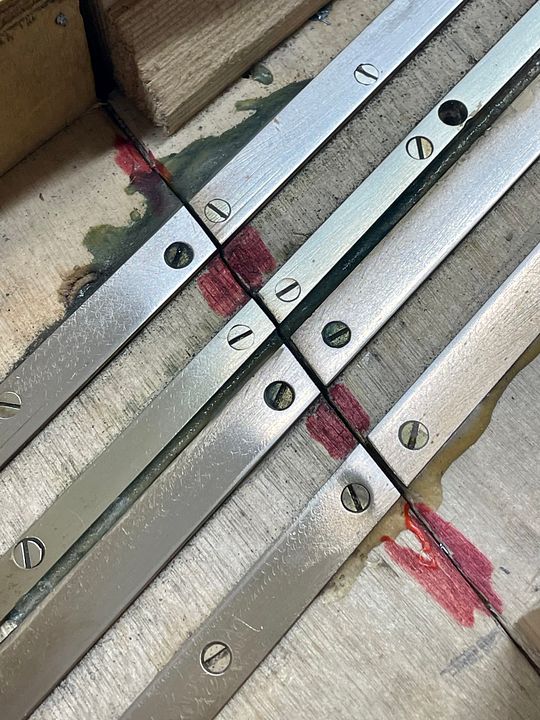
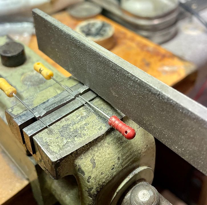
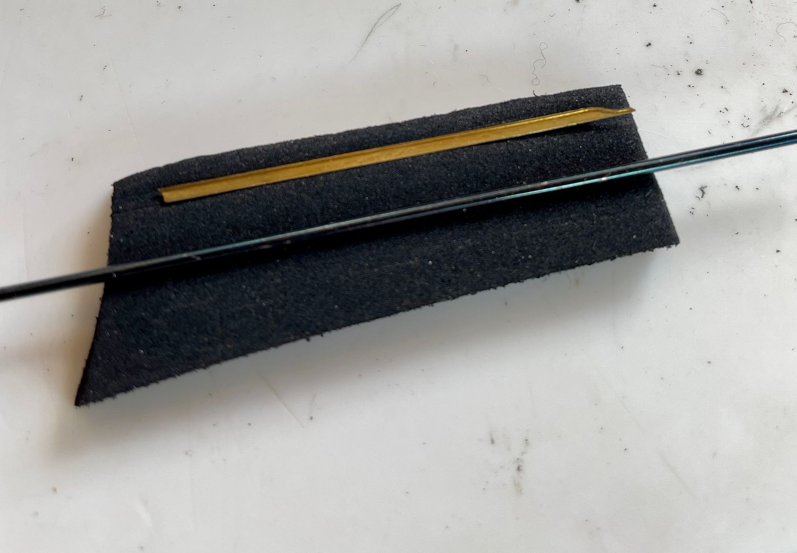
Rob Pulham has made one of these in 7mm scale, so I copied his excellent technique for forming the flares. This involved a 1mm diameter steel rod and some hard(ish) rubber sheet.
BBFDB4D0-85E1-47A9-9AEA-17360ECA348A.jpeg

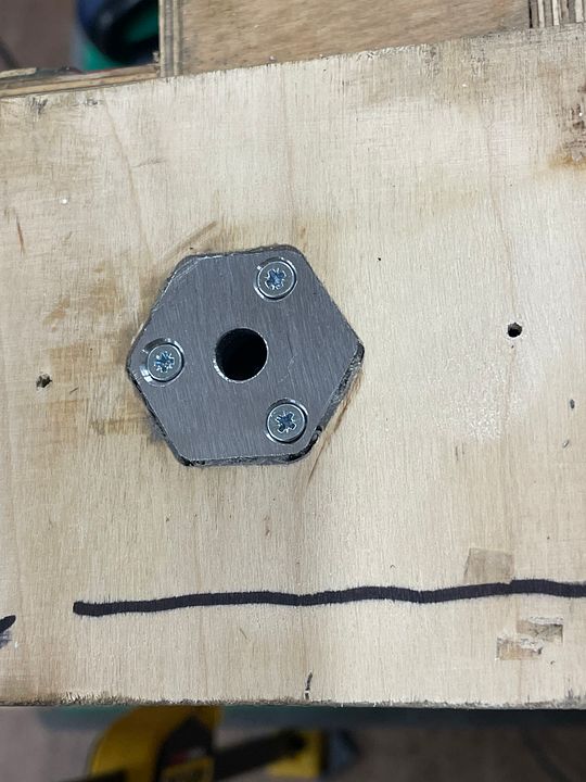
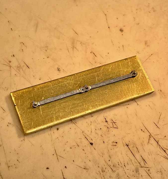
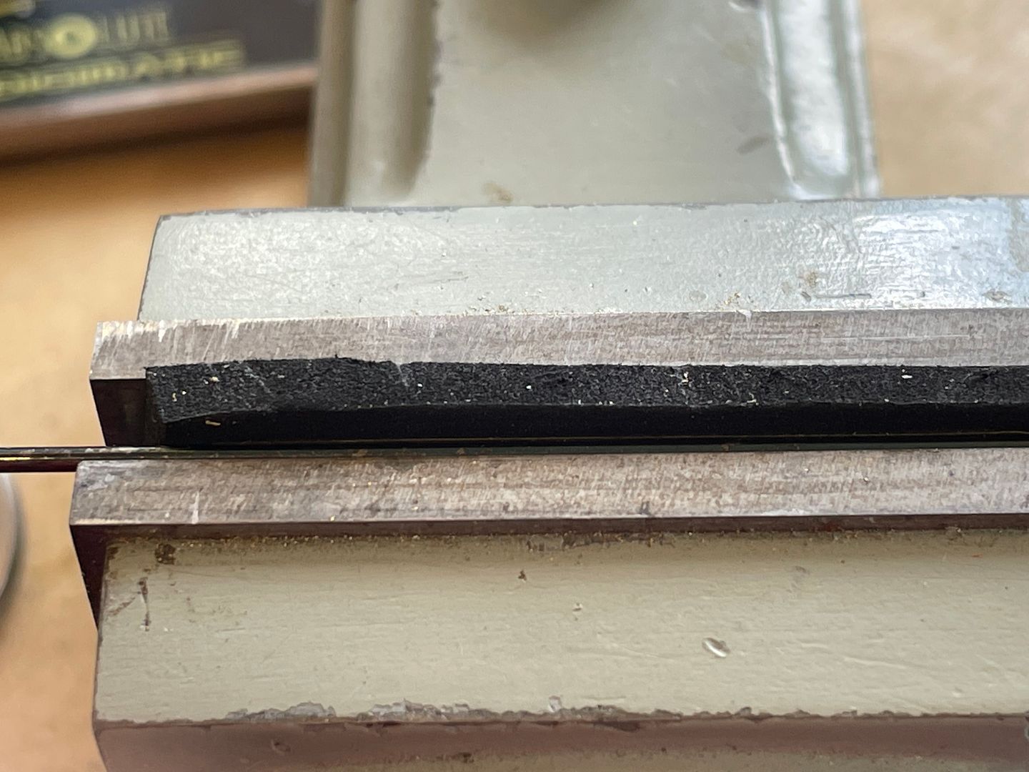
The rod and narrow flare component were carefully aligned in a vice and then squeezed hard.
BEB23D8D-CB0D-4FD7-8022-95C210490E11.jpeg

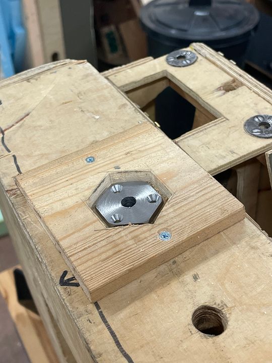
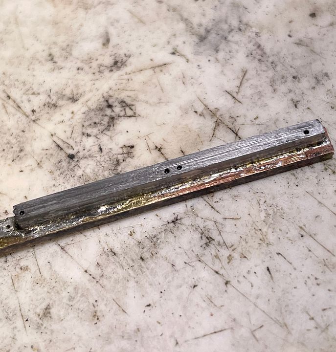
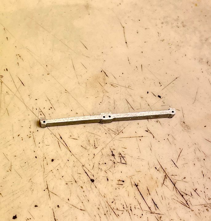
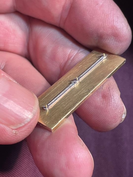
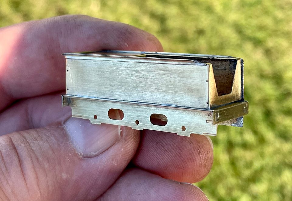
This translates the curvature of the rod into the brass strip to make the flare, as can be seen in the photo with them as separate components.
It was straightforward to solder these to the tender sides.

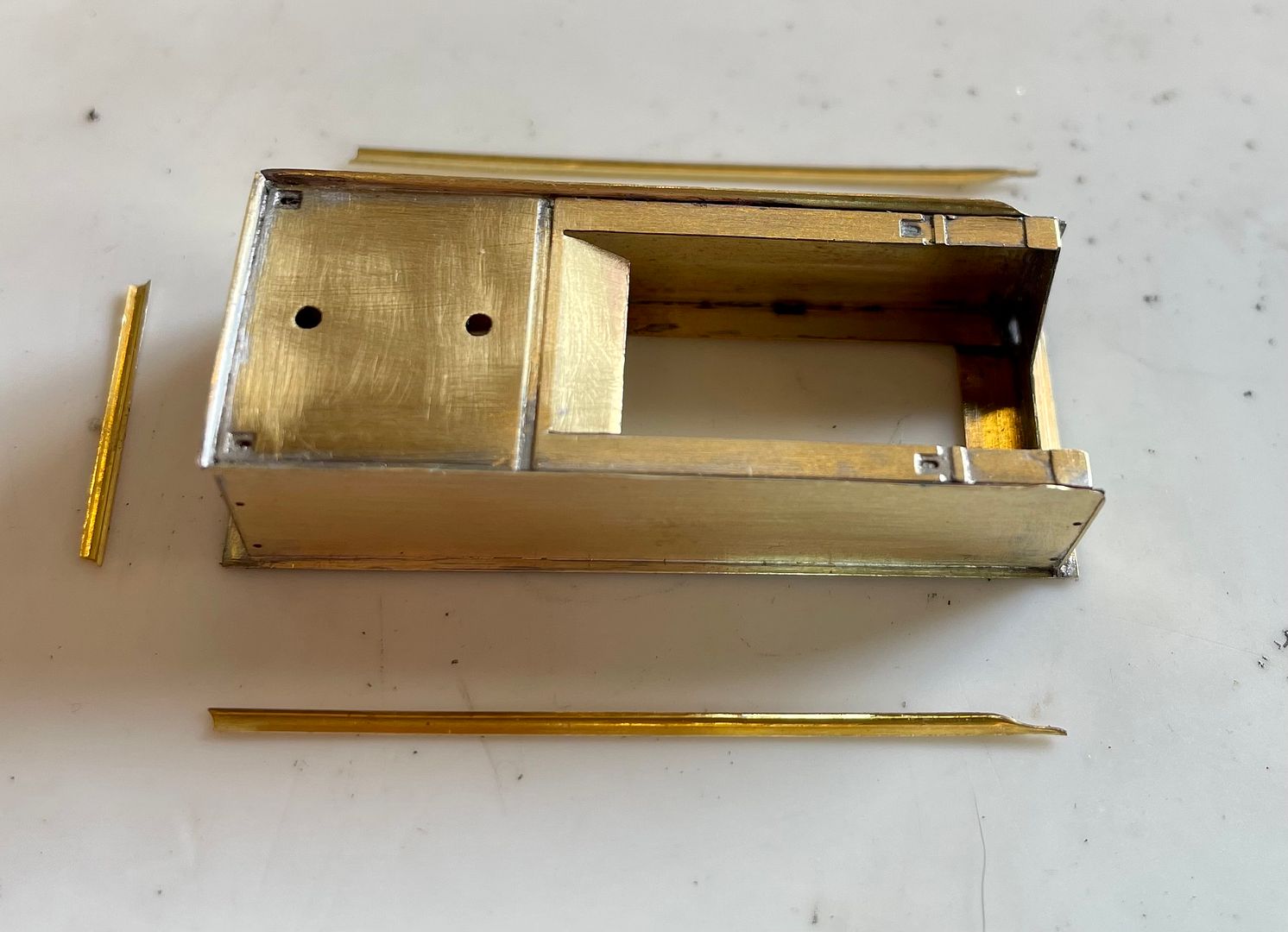
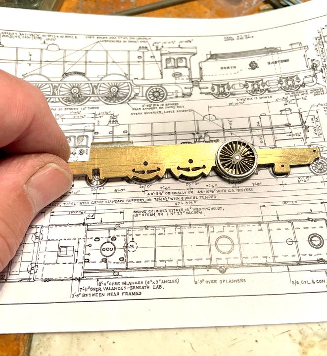
The underframe sides and ends complete the work so far. The kit produces some nicely understated flares: it’s easy to make them too large in 2mm scale. Having said that, Bob Jones is making some full height coal side plates, as the kit design is too low.

Work on the engine should continue at Missenden Abbey very shortly…

Tim
 
Last edited:

Chris Veitch

Western Thunderer
Beautiful work as usual Tim - I have to concede that my caravan visits usually involve leafing through MRJ backnumbers and “planning”...

Interesting to see that it’s going to be a 2-2-6-2 to get over the zero clearance around the rear bogie wheels.
 

michael mott

Western Thunderer
I always enjoy seeing the jeweler's saw being used, one of my favourite tools. And yes a nice view outside the workshop door. Tim Can you tell me more about the blue mat with the little square recesses.

Michael
 

Tim Watson

Western Thunderer

Tim Watson

Western Thunderer
After a day fiddling at Missenden I got the frames erected.
6C8E5633-AF25-4ED3-A407-AAB3802C5DC7.jpeg

The two bits of brass tube with 14BA bolts through them acting as spacers are used to set up the frames: they have been used for the last 40 years on all my 2mm scale locos. The long rods are to check out the alignment through the axle holes.
5BF74A71-1299-47C9-9592-2405009B7161.jpeg

The definitive spacers are double sided PCB soldered into place.
BAF409C4-ABB8-445B-8962-AE5B99163B63.jpeg

The springs and hangers are just about visible behind the wheels. A start has been made setting up some thick steel for the coupling rods: I like chunky valve gear, but I now need some new TC drills.

Tim
 

Tim Watson

Western Thunderer
Thanks Grahame. It’s a well worked formula that I turn the handle on; made easier by an excellent John Stevens mill/drill and modern TC drills.

Tim

Tim
 

Tim Watson

Western Thunderer
One recent little job at Missenden was to cross pin the worm wheel on Tony Gee’s lovely little Dean Goods (for Laurie Adam’s layout). The gear was slipping on the muff. It was therefore cross drilled between two of the teeth with a 0.4mm drill.
After drilling, some runny 24hr Araldite was worked into the hole, followed by a piece of 0.3mm wire.

Seemed to run OK the next day when the adhesive had set.

Tim

P.S. not sure why these images aren’t loading straight onto the page.
 
Last edited:

Tim Watson

Western Thunderer
Now for something quite different, a bit boring perhaps, but essential. A critical baseboard joint at the rear of Copenhagen Fields has never been finished to the correct standard. It now is. All part of getting ready for the MRC Open Day on 4th December.

The joiner system consists of a long 8mm bolt sliding in a 10mm tube (8.1mm bore) with locating collars either end. The bolt engages in a threaded collar at the far end. The two baseboards have different depths of end timbers; on the right hand side a box beam.

A hardwood drilling jig was screwed to the baseboard to guide a long 10mm drill through both of the aligned boards whilst they were held together with heavy clamps.

The end collars were turned from hex steel. A routing jig was screwed to the mating face of the baseboard to allow the router to follow the correct shape (with the collar removed). Each collar has a recess to locate the 10mm tube.

Routing the hex recess.

The end collar in place bedded in with 24hr epoxy resin with screws added after separating the boards.

The boards were bolted together with cling film between them and grease on the bolt to prevent a solid non-joint!

The M8 wing nuts were silver soldered onto the 8mm rod.

We now have good, solid, track alignment which should help reliability on this joint and speed up layout assembly. Conventional dowels would not work in this case as the 10’ long fiddle yard board ‘drops in’ between two fixed ends. These joiners are an improved version of the original pattern that were developed for CF and have been very successful over 35 years.


Tim
 

Tim Watson

Western Thunderer
CF is now fully erected ready for the MRC open day on Sunday (4/12/22). It’s a good opportunity to see the layout if anyone is interested.


I have resumed work on the Skittle Alley NER 4-6-2 class.


Two 1mm-thick steel strips were sweated together with a brass base, then drilled 0.5mm for the coupling rods by dead reckoning using the dials on the drilling table.


Once separated from the brass holding base, they were set up horizontally in the vice using endodontic instruments through the bearing holes. Some ‘stop’ cuts were made between the crank pin bosses and then the bulk of material removed with a course file.


The rods were roughed out before separating and trial fitting.


The set up worked well - if a little stiff from the excessively thick bearing surfaces on the rods - not a bad situation at this stage, as they will free up when reduced to 0.5mm thickness.

The next stage will see the rods reduced to scale dimensions and fluted.

Tim
 

Susie

Western Thunderer
Hi Tim,

What material are you using for the frames? It seems somewhat thicker than the old 20 thou PB.
 

Tim Watson

Western Thunderer
Hi Tim,

What material are you using for the frames? It seems somewhat thicker than the old 20 thou PB.
They are 33thou brass, Susie, which I prefer for steel axles. The phosphor bronze frames were 25thou - latterly running with the Association brass axle wheels.

Tim
 

Tim Watson

Western Thunderer
I have been shaping and fluting the coupling rods today on the NER 4-6-2 class

The first job was to mount them on a brass plate with analogue crank pins for location. A fine round file was then used to form the face radius either side of each bearing boss.


The rods were then reduced in thickness and finished by draw filing between the bosses.


A small marking gauge, fitted with a specially ground gramophone needle, was used to plane out the fluting between the bosses, using the side of the brass plate as a guide.


The rods were finally polished with crocus paper on the top and face.

I’ll probably look at the drive arrangements next.


It will be driven on the rear axle, as in this video.

Tim
 

michael mott

Western Thunderer
Tim, thank you for sharing the video of the fluting. A brilliant way to approach this task. I have filed it away for future reference.
Michael
 
Top