simond
Western Thunderer
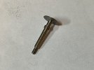
Here is the buffer problem. As you can see, the stem of the buffer extends beyond the cutaway in the frames. You may also see that the stem is a larger diameter than the major diameter of the thread, which is 10 BA / 1.6mm.

I therefore have to turn down the stem. I therefore have to hold it…. Given the shape, that’s a challenge.
The rather natty tray for the collets was printed on one of the work Bambu printers. Quite pleased with that. I shall do a similar tray for my BA taps & dies. And the metric ones when I get some more of them.
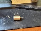
the brass round is 5/16” or a midge’s less than 8mm. I cleaned the outside and parted off a slice, which I then chucked, centre drilled, drilled 1.93mm and counter drilled 2.93, and then sawed through to make a split bush. This fits in the collet chuck nicely.

And it worked, though not without some very unexpected runout. And a significant difference in the buffer shank diameters, requiring the split collet to be opened up. Fortunately, by chance, I’d done the smaller one first.
Don’t understand the runout, and will have to investigate. Hopefully I managed to include some swarf in the collet chuck.
Not in the mood tonight however,
and to add to the snagging / to do list, I have the pickups, but I do not have a vac pipe and a steam heat hose. No worries, Kettering soon…

Simon
I therefore have to turn down the stem. I therefore have to hold it…. Given the shape, that’s a challenge.
The rather natty tray for the collets was printed on one of the work Bambu printers. Quite pleased with that. I shall do a similar tray for my BA taps & dies. And the metric ones when I get some more of them.
the brass round is 5/16” or a midge’s less than 8mm. I cleaned the outside and parted off a slice, which I then chucked, centre drilled, drilled 1.93mm and counter drilled 2.93, and then sawed through to make a split bush. This fits in the collet chuck nicely.
And it worked, though not without some very unexpected runout. And a significant difference in the buffer shank diameters, requiring the split collet to be opened up. Fortunately, by chance, I’d done the smaller one first.
Don’t understand the runout, and will have to investigate. Hopefully I managed to include some swarf in the collet chuck.
Not in the mood tonight however,
and to add to the snagging / to do list, I have the pickups, but I do not have a vac pipe and a steam heat hose. No worries, Kettering soon…
Simon


")


